Content .. 1743 1744 1745 1746 ..
Mitsubishi Outlander GS45X. Manual - part 1745
A/T KEY INTERLOCK AND SHIFT LOCK MECHANISMS
TSB Revision
AUTOMATIC TRANSAXLE
23C-285
A/T KEY INTERLOCK AND SHIFT LOCK MECHANISMS
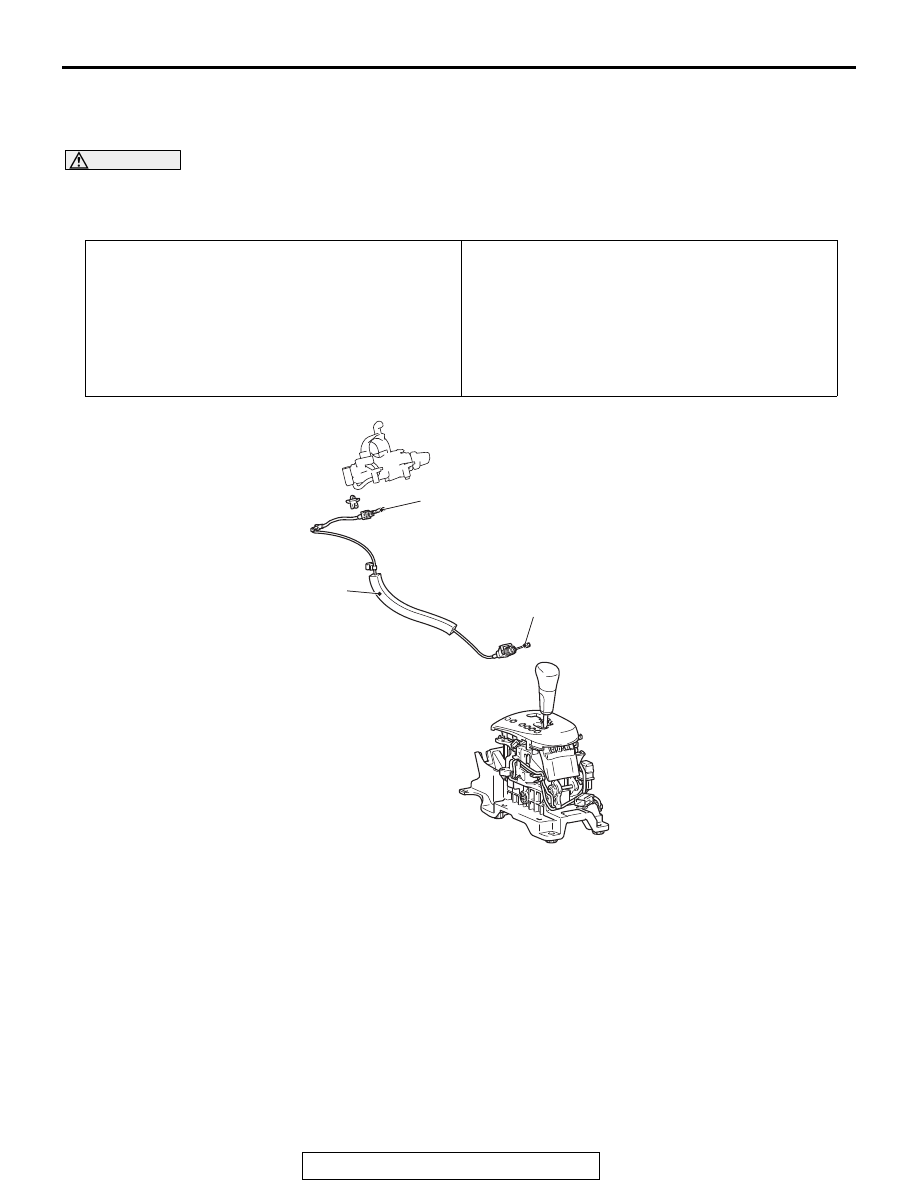
REMOVAL AND INSTALLATION
M1231036300112
WARNING
When removing and installing the transaxle
control cable and shift lock cable unit, be
careful not to hit the SRS-ECU.
REMOVAL SERVICE POINT
.
<<A>> KEY INTERLOCK CABLE (STEERING
SIDE) REMOVAL
Turn the ignition switch to the "ACC" position and then pull the
key interlock cable out from the ignition key cylinder.
Pre-removal operation
• Steering column lower cover and side lower panel assem-
bly removal (Refer to GROUP 52A
− Instrument Panel
Assembly
.)
• Front floor console assembly removal (Refer to GROUP
52A
− Floor Console Assembly
Post-installation operation
• Steering column lower cover and side lower panel assem-
bly installation (Refer to GROUP 52A
− Instrument Panel
Assembly
.)
• Front floor console assembly installation (Refer to
GROUP 52A
− Floor Console Assembly
.)
• Key interlock mechanism check (Refer to
• Shift lock mechanism check (Refer to
.)
• Selector lever operation check (Refer to
.)
AC607789AB
1
2
3
Removal steps
>>B<<
1.
Key interlock cable connection
(selector lever side)
<<A>> >>A<<
2.
Key interlock cable connection
(steering side)
3.
Key interlock cable
Removal steps (Continued)