Mitsubishi Outlander GS45X. Manual - part 1743


  Index      Mitsubishi     Mitsubishi Outlander GS45X - service repair manual


Search            


Content   ..  1741  1742  1743  1744   ..


Mitsubishi Outlander GS45X. Manual - part 1743


ON-VEHICLE SERVICE

TSB Revision

AUTOMATIC TRANSAXLE

23C-277

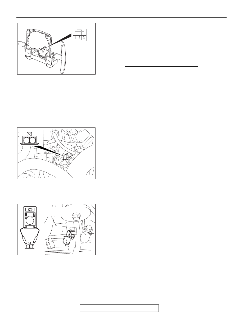
3. Check for continuity between the paddle shift switch 

connector terminals.

Standard value:

4. In the cases other than the above, replace the paddle shift 

assembly.

ELECTRONIC CONTROL COUPLING SOLENOID 
(FRONT) CHECK <VEHICLES WITH S-AWC>

M1235005000021

1. Disconnect the B-28 connector, and measure the resistance 

value between the connector terminals on the electronic 
control coupling side. If the measured resistance value is out 
of the standard value range, replace the transfer assembly 
(Refer to 

P.23C-292

).

Standard value: 1.8 

 4.0 Ω

2. Measure the resistance value between the connector 

terminal No.1 on the electronic control coupling side and the 
body ground. If the continuity exists, replace the transfer 
assembly (Refer to 

P.23C-292

).

ELECTRONIC CONTROL COUPLING SOLENOID 
(CENTER) CHECK <VEHICLES WITH S-AWC>

M1235005200014

1. Disconnect the D-138 connector, and measure the 

resistance value between the connector terminals on the 
electronic control coupling side. If the measured resistance 
value is out of the standard value range, replace the 
electronic control coupling (Refer to 

P.27C-97

).

Standard value: 1.6 

 3.7 Ω

2. Measure the resistance value between the connector 

terminal No.1 on the electronic control coupling side and the 
body ground. If the continuity exists, replace the electronic 
control coupling (Refer to 

P.27C-97

).

Paddle shift lever

Terminal 
number

Resistance 
value

Upshift and hold the 
lever.

− 2

Continuity 
exists. (2 

Ω 

or less)

Downshift and hold 
the lever.

− 3

No operation

No continuity between the 
terminals

AC607778AB

AC900389

2

1

AB

AC707679

2

1

AB

Electronic
control coupling

ON-VEHICLE SERVICE

TSB Revision

AUTOMATIC TRANSAXLE

23C-278

SELECTOR LEVER OPERATION CHECK

M1231001300824

1. Put on the parking brake.
2. Move the selector lever to every range and check that the 

lever moves smoothly with secure feel of engagement.

3. Make sure that the engine starts when the selector lever is in 

the "N" or "P" range, and does not start when the selector 
lever is in other range.

4. Start the engine. Release the parking brake.
5. Make sure that the vehicle moves forward when the selector 

lever is moved from the "N" range to "D" range, or to the 1st 
to 6th speed in the sport mode. Also make sure that the 
vehicle moves backward when the selector lever is moved 
from the "N" to "R" range.

6. Stop the engine.
7. Turn ON the ignition switch, and move the selector lever 

from the "P" to "R" range. Check that the backup light comes 
on and the tone alarm sounds at this time.
NOTE: Since the vehicle is equipped with the A/T 
wrong-operation preventive device, the selector lever cannot 
be moved out of the "P" position without depressing the 
brake pedal after turning "ON" the ignition switch.

KEY INTERLOCK MECHANISM 
CHECK/ADJUSTMENT

M1231036000025

1. Carry out the following check.

2. If the normal conditions are not obtained after performing the 

above operations, install the key interlock cable in the 
following procedures. (Automatic adjustment)

(1) Disconnect the key interlock cable connection (selector 

lever side).(Refer to 

P.23C-285

.)

AC703193

P

R

N

D

AB

: Turn the ignition switch to the
 "ON" position, and operate the lever
 while depressing the brake pedal. 

: Only shifting

: Automatic return

Inspectio

procedur
e

Check conditions

Items to be checked (Normal conditions)

1

Brake pedal: 
Depress

Ignition switch position: 
"LOCK" (OFF) or removed

The selector lever cannot be moved out of "P" 
position.

2

Ignition switch position: 
"ON"

The selector lever can be moved from "P" 
position to other positions smoothly.

3

Transmission range: Other than P

The ignition switch cannot be turned to the 
"LOCK" (OFF) position.

4

Transmission range: P

The ignition switch can be turned to the "LOCK" 
(OFF) position smoothly.

ON-VEHICLE SERVICE

TSB Revision

AUTOMATIC TRANSAXLE

23C-279

CAUTION

Leave the ignition switch in the "LOCK" (OFF) position 
until the key interlock cable installation is completed.

(2) Move the selector lever to the "P" position and turn the 

ignition switch to the "LOCK" (OFF) position.

(3) Install the tip of the key interlock cable to the lock cam of 

the selector lever assembly, taking care not to twist the 
inner cable.

(4) Install the adjuster case with its lock guide pulled up 

(unlocked).

(5) Securely push down the lock guide to lock it.

NOTE: The lock position of the key interlock cable is 
automatically adjusted by a spring.

AC607780AB

Spring

Unlock

Lock guide

Adjuster case

Inner cable

Adjuster case

Key inter lock cable

Lock guide

Lock cam

Lock

View A

A

ON-VEHICLE SERVICE

TSB Revision

AUTOMATIC TRANSAXLE

23C-280

SHIFT LOCK MECHANISM CHECK

M1231036100185

SYSTEM CHECK

Inspection 
procedure

Check conditions

Items to be checked (Normal 
conditions)

Possible cause of 
abnormality

1

Brake pedal not 
depressed

Ignition 
switch: 
"LOCK", 
"ACC" or 
removed

The selector lever cannot be 
moved out of the "P" position

• Abnormality in the shift lock 

link (stuck, disengaged, 
broken, etc.)

• Abnormality in the electrical 

circuit

• Abnormality in the key 

interlock mechanism

2

Brake pedal 
depressed

• Abnormality in the electrical 

circuit

• Abnormality in the key 

interlock mechanism

3

Brake pedal not 
depressed

Ignition 
switch: 
ON

• Abnormality in the shift lock 

link (stuck, disengaged, 
broken, etc.)

• Abnormality in the electrical 

circuit

4

Brake pedal 
depressed

The selector lever can be 
moved from the "P" position to 
other positions smoothly.

• Abnormality in the shift lock 

link (stuck, disengaged, 
broken, etc.)

• Abnormality in the electrical 

circuit

5

Shift lock release 
button pressed

• Abnormality in the shift lock 

link (stuck, disengaged, 
broken, etc.)

6

Brake pedal 
depressed / not 
depressed

The selector lever can be 
moved from the "R" position to 
the "P" position smoothly.

• Abnormality in the shift lock 

link (stuck, disengaged, 
broken, etc.)


Content   ..  1741  1742  1743  1744   ..