Mitsubishi Outlander GS45X. Manual - part 1702


  Index      Mitsubishi     Mitsubishi Outlander GS45X - service repair manual


Search            


Content   ..  1700  1701  1702  1703   ..


Mitsubishi Outlander GS45X. Manual - part 1702


AUTOMATIC TRANSAXLE DIAGNOSIS <A/T>

TSB Revision

AUTOMATIC TRANSAXLE

23C-113

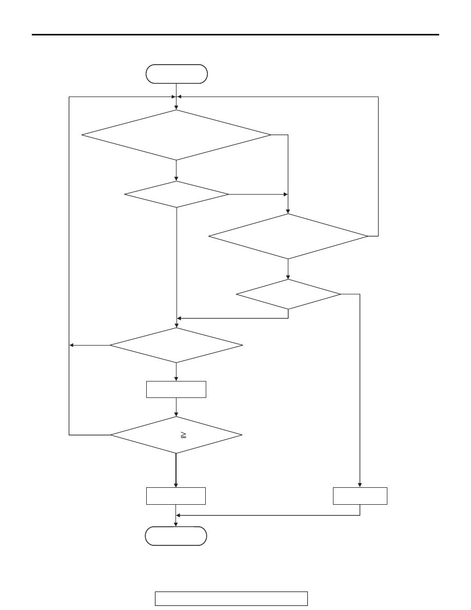
LOGIC FLOW CHARTS (Monitor Sequence)

.

AC802676

Good

Fail counter up

END

No

No

No

No

No

No

Yes

Yes

Yes

Yes

Yes

Yes

START

Status is ''off''

Status is ''on''

All secondary parameters are
in the enable condition for
              ''Stuck-off''.

All secondary parameters
are in the enable condition
          for ''Stuck-on''.

Continuous failure for 2 secs.

Fail counter     2 times

Malfunction

AUTOMATIC TRANSAXLE DIAGNOSIS <A/T>

TSB Revision

AUTOMATIC TRANSAXLE

23C-114

DTC SET CONDITIONS

Check Conditions <Stuck-off>

• Transmission range switch position: R

• Gear position: reverse

• Time after shift changing finish: 2 seconds or 

more

Judgment Criteria <Stuck-off>

• Low-reverse brake pressure switch status: OFF 

(2 seconds 

× 2times)

Check Conditions <Stuck-on>

• Transmission range switch position: D

• Gear position: 1st, 2nd, 3rd, 4th, 5th, 6th

• Time after shift changing finish: 2 seconds or 

more

Judgment Criteria <Stuck-on>

• Low-reverse brake pressure switch status: ON (2 

seconds 

× 2times)

.

OBD-II DRIVE CYCLE PATTERN

Reverse gear driving for 2 seconds or more

.

TROUBLESHOOTING HINTS (THE MOST 
LIKELY CAUSES FOR THIS CODE TO BE 
SET ARE:)

• Malfunction of the low-reverse brake pressure 

switch system circuit

• Damaged harness or connector

• Malfunction of the TCM

• Malfunction of the low-reverse brake pressure 

switch system (valve body assembly)

• Malfunction of the valve body assembly, abnor-

mal hydraulic circuit valve.

CAUTION

For the incomplete gear shifting and slippage, 
first refer to the SYMPTOM CHART 

P.23C-28

.

DIAGNOSIS

STEP 1. Check the DTC.
Q: Is the DTC other than the pressure switch set? (Is the 

code other than P0846, P0876, and P0988 set?)
YES : 
Check and repair the relevant DTC system.
NO :  Go to Step 2.

STEP 2. Check the TCM terminal voltage.
[C-37 TCM connector (vehicle side, connected)]
Measure the voltage between C-37 terminal No. 43 and body 
ground.

• Low-reverse brake engaged: 0 V

• Other than above: Battery positive voltage

Q: Is the check result normal?

YES : Go to Step 3.
NO :  Go to Step 7.

STEP 3. Check between the TCM connector and A/T 
control solenoid valve assembly.
Check for continuity between C-37 TCM connector and B-111 
A/T control solenoid valve assembly connector.
NOTE: Prior to the wiring harness inspection, check the inter-
mediate connectors A-12 and repair that if necessary.

• Between C-37 terminal No. 43 and B-111 terminal No. 7: 

Continuity exists.

When the continuity check result is OK, check that the wiring 
harness is not shorted to the body and other wiring harness.
Q: Is the check result normal?

YES : Go to Step 4.
NO :  Repair or replace the failure section.

AUTOMATIC TRANSAXLE DIAGNOSIS <A/T>

TSB Revision

AUTOMATIC TRANSAXLE

23C-115

STEP 4. Check the TCM, A/T control solenoid valve 
assembly connector pin terminals, and the connection 
status.
Q: Is the check result normal?

YES : Go to Step 5.
NO :  Repair or replace the failure section.

STEP 5. Check between the A/T control solenoid valve 
assembly connector and low-reverse brake pressure 
switch.
Check for continuity between the B-111 A/T control solenoid 
valve assembly connector terminals and the low-reverse brake 
pressure switch connector terminals.

• Between B-111 terminal No. 7 and low-reverse brake pres-

sure switch: Continuity exists.

When the continuity check result is OK, check that the wiring 
harness is not shorted to the body and other wiring harness.
Q: Is the check result normal?

YES : Go to Step 6.
NO :  Repair or replace the failure section.

STEP 6. Check the low-reverse brake pressure switch 
body ground.
Check for continuity between the low-reverse brake pressure 
switch body and ground.

• Between the low-reverse brake pressure switch body and 

body ground: Continuity exists.

Q: Is the check result normal?

YES : Replace the valve body assembly, and then go to 

Step 8.

NO :  Repair or replace the failure section.

STEP 7. Check the TCM, A/T control solenoid valve 
assembly connector pin terminals, and the connection 
status.
Q: Is the check result normal?

YES : Go to Step 9.
NO :  Repair or replace the failure section.

STEP 8. Erase the DTC code, and drive the vehicle for a 
while.
Check that the normal code is displayed.
Q: Is the check result normal?

YES : The procedure is complete.
NO :  Replace the TCM.

AUTOMATIC TRANSAXLE DIAGNOSIS <A/T>

TSB Revision

AUTOMATIC TRANSAXLE

23C-116

STEP 9. Erase the DTC code, and drive the vehicle for a 
while.
Check that the normal code is displayed.
Q: Is the check result normal?

YES : The procedure is complete.
NO :  Return to START.

DTC P1705: Throttle Position Sensor Information (Engine)

.

DESCRIPTIONS OF MONITOR METHODS

With the vehicle speed 5 km/h (3.1 mph) or more or 
the output shaft speed sensor normal, and after the 
A/T-ECU startup, when approximately 1 second has 
elapsed, if the TPS fail signal is received for 5 sec-
onds, or the APS fail signal is received for 3 seconds 
from the engine ECU.

.

MONITOR EXECUTION

• Vehicle speed 5 km/h (3.1 mph) or more

.

MONITOR EXECUTION CONDITIONS 
(OTHER MONITOR AND SENSOR)

Other Monitor (There is no temporary DTC stored 

in memory for the item monitored below)

• Not applicable

Sensor (The sensor below is determined to be 

normal)

• Not applicable

.


Content   ..  1700  1701  1702  1703   ..