Content .. 1692 1693 1694 1695 ..
Mitsubishi Outlander GS45X. Manual - part 1694
AUTOMATIC TRANSAXLE DIAGNOSIS <A/T>
TSB Revision
AUTOMATIC TRANSAXLE
23C-81
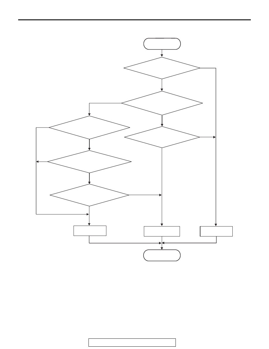
LOGIC FLOW CHARTS (Monitor Sequence)
.
DTC SET CONDITIONS
Check Conditions <Circuit continuity ground>
• Gear position: 1st to 4th.
Judgment Criteria <Circuit continuity ground>
• Low clutch linear solenoid valve actual current:
more than 1.7 A (1 second)
Check Conditions <Circuit continuity open>
• Gear position: 1st to 4th.
• Low clutch linear solenoid valve activation com-
mand: more than 937 mA
Judgment Criteria <Circuit continuity open>
• Low clutch linear solenoid valve actual current:
less than 500 mA. (5 seconds)
.
OBD-II DRIVE CYCLE PATTERN
Drive in 1st to 4th gears. Maintain each shift range
for approximately 10 seconds.
.
AC802672
Good
Malfunction
END
No
No
No
Good
No
No
No
Yes
Yes
Yes
Yes
Yes
Yes
START
Continuous failure for 1 sec.
Continuous failure for 5 secs.
Actual solenoid current > 1.7 A
Gear position is 1st to 4th
Actual solenoid
current < 500 mA
Solenoid activation
command > 937 mA