Mitsubishi Outlander GS45X. Manual - part 1622


  Index      Mitsubishi     Mitsubishi Outlander GS45X - service repair manual


Search            


Content   ..  1620  1621  1622  1623   ..


Mitsubishi Outlander GS45X. Manual - part 1622


DIAGNOSIS

TSB Revision

CVT

23A-45

DIAGNOSTIC FUNCTION

TCM conducts fault detection by monitoring the ter-
minal voltage of the transmission fluid temperature 
sensor.

• <P0712>: If transmission fluid temperature 

equals or exceeds specified value, TCM judges 
that transmission fluid temperature sensor has a 
failure.

• <P0713>: If transmission fluid temperature is 

below specified value even after test driving for 
more than the specified period, the TCM judges 
that the transmission fluid temperature sensor 
has a failure.

.

DESCRIPTIONS OF MONITOR METHODS 
<P0712>

• TCM detects the fluid temperature 180°C (356°F) 

or more for 5 seconds.

.

MONITOR EXECUTION <P0712>

• Continuous

.

MONITOR EXECUTION CONDITIONS 
(OTHER MONITOR AND SENSOR) 
<P0712>

Other Monitor (There is no temporary DTC stored 

in memory for the item monitored below)

• P0741: Abnormality in lockup function

• P0746: Abnormality in hydraulic control system 

function

• P0841: Abnormality in line pressure sensor func-

tion

Sensor (The sensor below is determined to be 

normal)

• Not applicable

.

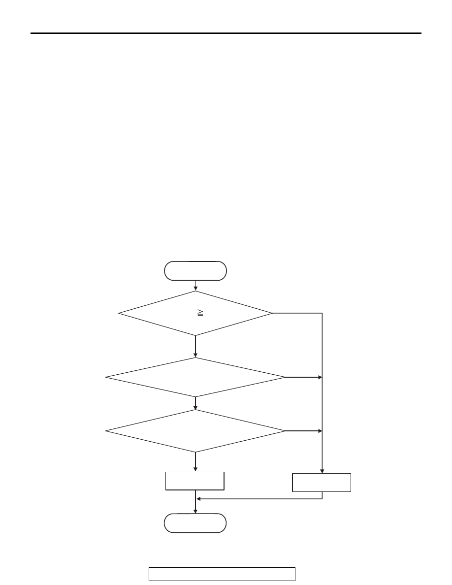
LOGIC FLOW CHARTS (Monitor Sequence) <P0712>

.

AC710007

START

Yes

No

Transmission fluid    180 ˚C (356 ˚F)

Yes

No

Yes

No

Good

Malfunction

END

Continuous failure for 5 sec

All secondary parameters
are in the enable condition.

DIAGNOSIS

TSB Revision

CVT

23A-46

DTC SET CONDITIONS <P0712>

Check Conditions

• Voltage of battery: 9 volts or more.

• Voltage of battery: 16 volts or less.

JUDGMENT CRITERIA

• Value of temperature of transmission fluid: 180°C 

(356

°F) or more. (5 seconds)

.

OBD-II DRIVE CYCLE PATTERN <P0712>

Ignition switch : ON (start the engine and keep it for 
10 seconds or more)

.

DESCRIPTIONS OF MONITOR METHODS 
<P0713>

• TCM detects the fluid temperature −40°C (−40°F) 

or less for 5 seconds.

.

MONITOR EXECUTION <P0713>

• Vehicle speed 10 km/h or more has been 

detected during 1 drive cycle

.

MONITOR EXECUTION CONDITIONS 
(OTHER MONITOR AND SENSOR) 
<P0713>

Other Monitor (There is no temporary DTC stored 

in memory for the item monitored below)

• P0741: Abnormality in lockup function

• P0746: Abnormality in hydraulic control system 

function

• P0841: Abnormality in line pressure sensor func-

tion

Sensor (The sensor below is determined to be 

normal)

• Not applicable

.

DIAGNOSIS

TSB Revision

CVT

23A-47

LOGIC FLOW CHARTS (Monitor Sequence) <P0713>

.

DTC SET CONDITIONS <P0713>

Check Conditions

• After vehicle speed: 10 km/h (6.2 mph) or more.

• Voltage of battery: 9 volts or more.

• Voltage of battery: 16 volts or less.

JUDGMENT CRITERIA

• Value of temperature of transmission fluid: −40°C 

(-40

°F) or less. (5 seconds)

.

OBD-II DRIVE CYCLE PATTERN <P0713>

transmission range: D (Drive the vehicle for 10 sec-
onds or more while the accelerator opening angle is 
20% or more)

.

PROBABLE CAUSES

• Malfunction of the valve body assembly (Faulty 

transmission fluid temperature sensor)

• Damaged wiring harness and connectors

• Malfunction of TCM

AC710008

START

Yes

No

Transmission fluid    -40 ˚C (-40 ˚F)

Yes

No

Yes

No

Yes

No

Good

Malfunction

END

After vehicle speed    10 km/h (6.2 mph)

Continuous failure for 5 sec

All secondary parameters
are in the enable condition.

DIAGNOSIS

TSB Revision

CVT

23A-48

DIAGNOSTIC PROCEDURE

STEP 1. M.U.T.-III data list
Item 5: Transmission fluid temperature sensor signal (Refer to 
Data List Reference Tabl

P.23A-127

).

Q: Is the check result normal?

YES : Intermittent malfunction
NO :  Go to Step 2.

STEP 2. Check the following connector:

• B-125 Transaxle assembly connector

• C-37 TCM connector

• A-12 Intermediate connector

Check the terminals for a contact status problem and internal 
short circuit.
Q: Is the check result normal?

YES : Go to Step 3.
NO :  Repair the defective connector.

STEP 3. Check for open circuit and short to ground in the 
wiring harness between the CVT assembly connector and 
the TCM connector
Between B-125 CVT assembly connector (terminal No.17) and 
C-37 TCM connector (terminal No.50)
Q: Is the check result normal?

YES : Go to Step 4.
NO :  Repair the wiring harness.

STEP 4. Check for open circuit in the wiring harness 
between the CVT assembly connector and the TCM 
connector
Between B-125 CVT assembly connector (terminal No.19) and 
C-37 TCM connector (terminal No.48)
Q: Is the check result normal?

YES : Go to Step 5.
NO :  Repair the wiring harness.

STEP 5. Transmission fluid temperature sensor check
Refer to 

P.23A-147

.

Q: Is the check result normal?

YES : Go to Step 6.
NO :  Replace the valve body assembly.

STEP 6. Symptom recheck after erasing diagnostic trouble 
code
Q: Is the check result normal?

YES : Intermittent malfunction
NO :  Replace TCM.


Content   ..  1620  1621  1622  1623   ..