Mitsubishi Outlander GS45X. Manual - part 1619


  Index      Mitsubishi     Mitsubishi Outlander GS45X - service repair manual


Search            


Content   ..  1617  1618  1619  1620   ..


Mitsubishi Outlander GS45X. Manual - part 1619


DIAGNOSIS

TSB Revision

CVT

23A-33

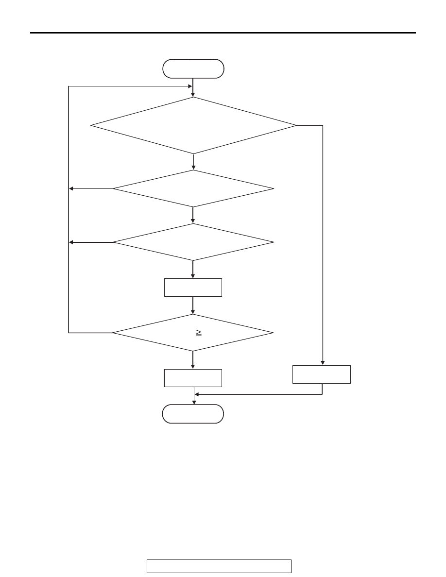
LOGIC FLOW CHARTS (Monitor Sequence)

.

DTC SET CONDITIONS

Check Conditions

• Vehicle speed: 30 km/h (19 mph) or more.

• Voltage of battery: 9 volts or more.

• Voltage of battery: 16 volts or less.

JUDGMENT CRITERIA

• The change of stoplight switch signal during driv-

ing cycle: no occurrence (10 seconds 

× 2 times).

.

OBD-II DRIVE CYCLE PATTERN

Drive the vehicle for 10 seconds or more at 30 km/h 
(19 mph) or higher (2 drive cycle)

.

PROBABLE CAUSES

• Malfunction of the CAN bus

• Malfunction of the stoplight switch

• Damaged wiring harness and connectors

• Malfunction of TCM

• Malfunction of ETACS-ECU

AC802601

START

Yes

No

The change of stoplight switch signal
non occurrence during driving cycle.  

Continuous failure for 10 sec.

All secondary parameters
are in the enable condition.

Yes

No

Yes

Yes

Yes

No

No

Good

Malfunction

Fail counter up

END

Fail counter     2 times.

DIAGNOSIS

TSB Revision

CVT

23A-34

DIAGNOSTIC PROCEDURE

STEP 1. Using scan tool MB991958, diagnose the CAN bus 
line.
Use scan tool to perform the CAN bus diagnosis.
Q: Is the check result normal?

YES : Go to Step 2.
NO :  Repair the CAN bus lines (Refer to GROUP 54C, 

Troubleshooting 

− Diagnostic Trouble Code Chart 

P.54C-19

).

STEP 2. M.U.T.-III data list
Item 50: Brake switch

OK: The service data changes in response to the 
brake operation.

Q: Is the check result normal?

YES : Intermittent malfunction
NO :  Go to Step 3.

STEP 3. Check the following connector:

• C-304 ETACS-ECU connector

• C-312 ETACS-ECU connector

• C-124 Stoplight switch connector

• C-133 Stoplight relay connector

Check the contact status of the terminals.
Q: Is the check result normal?

YES : Go to Step 4.
NO :  Repair the defective connector.

STEP 4. Stoplight Switch Check
Refer to GROUP 35A, Brake Pedal 

P.35A-27

.

Q: Is the check result normal?

YES : Go to Step 5.
NO :  Replace the stoplight switch.

STEP 5. Check for open circuit in the wiring harness 
between the stoplight switch connector and the 
ETACS-ECU connector.
Between C-124 Stoplight switch connector (terminal No.1) and 
C-304 ETACS-ECU harness-side connector (terminal No.1)
Q: Is the check result normal?

YES : Go to Step 6.
NO :  Repair the wiring harness.

DIAGNOSIS

TSB Revision

CVT

23A-35

STEP 6. Check for open circuit or short to ground in wiring 
harness between the stoplight switch connector and the 
ETACS-ECU
Between C-124 Stoplight switch connector (terminal No. 2) and 
C-312 ETACS-ECU harness-side connector (terminal No. 16)
Q: Is the check result normal?

YES : Go to Step 7.
NO :  Repair the wiring harness.

STEP 7. Symptom recheck after erasing diagnostic trouble 
code
Q: Is the check result normal?

YES : Intermittent malfunction
NO :  Replace the ETACS-ECU, and then go to Step 8.

STEP 8. Symptom recheck after erasing diagnostic trouble 
code
Q: Is the check result normal?

YES : Intermittent malfunction
NO :  Replace TCM.

DIAGNOSIS

TSB Revision

CVT

23A-36

DTC P0705: Malfunction of Transmission Range Switch

IGNITION
SWITCH (IG1)

IG1
RELAY

ETACS-ECU

TRANSMISSION
RANGE
SWITCH

TRANSAXLE 
CONTROL
MODULE

Transmission range switch system circuit


Content   ..  1617  1618  1619  1620   ..