Mitsubishi Outlander GS45X. Manual - part 1615


  Index      Mitsubishi     Mitsubishi Outlander GS45X - service repair manual


Search            


Content   ..  1613  1614  1615  1616   ..


Mitsubishi Outlander GS45X. Manual - part 1615


DIAGNOSIS

TSB Revision

CVT

23A-17

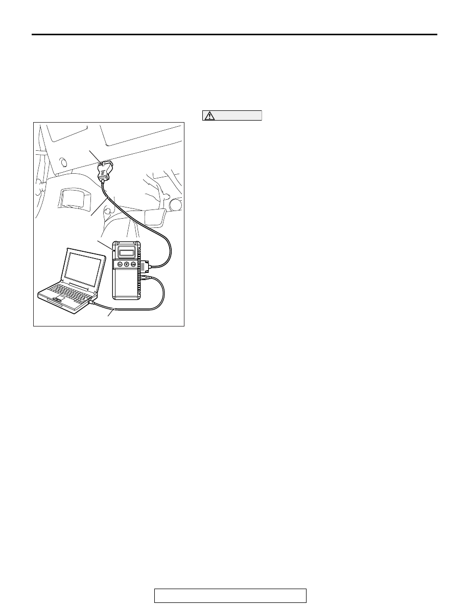
HOW TO DIAGNOSE THE CAN BUS LINES

Required Special Tools:

• MB991958: Scan Tool (M.U.T.-III Sub Assembly)

• MB991824: V.C.I.

• MB991827: M.U.T.-III USB Cable

• MB991910: M.U.T.-III Main Harness A

CAUTION

To prevent damage to scan tool MB991958, always turn the 
ignition switch to the "LOCK" (OFF) position before con-
necting or disconnecting scan tool MB991958.
1. Connect scan tool MB991958 to the data link connector.
2. Turn the ignition switch to the "ON" position.
3. Select "CAN bus diagnosis" from the start-up screen.
4. When the vehicle information is displayed, confirm that it 

matches the vehicle whose CAN bus lines will be 
diagnosed.

• If they match, go to step 8.

• If not, go to step 5.

5. Select the "view vehicle information" button.
6. Enter the vehicle information and select the "OK" button.
7. When the vehicle information is displayed, confirm again 

that it matches the vehicle whose CAN bus lines will be 
diagnosed.

• If they match, go to step 8.

• If not, go to step 5.

8. Select the "OK" button.
9. When the optional equipment screen is displayed, choose 

the one which the vehicle is fitted with, and then select the 
"OK" button.

HOW TO INITIALIZE CVT LEARNED VALUE

M1231202400282

.

PURPOSE

After the CVT assembly, engine assembly, and valve 
body assembly are replaced, their learned value 
must be initialized. The initialization procedure is as 
below.

.

INITIALIZATION PROCEDURE

1. Move the selector lever to the "P" range and turn 

the ignition switch to the "LOCK" (OFF) position. 
Then, connect scan tool to the data link connector.

2. Turn the ignition switch to the "ON" position, and 

then move the selector lever to the "R" range.

3. Depress the accelerator pedal while depressing 

the brake pedal. (Engine is not running.) Using 
the M.U.T.-III, execute the clear DTC function for 
the CVT-ECU (even if no code is set).

NOTE: Performing initialization of the learned value 
will also erase the diagnostic trouble code.

AC608435

Data link connector

MB991827

MB991824

MB991910

AB

DIAGNOSIS

TSB Revision

CVT

23A-18

LEARNING PROCEDURE FOR CVT HYDRAULIC CONTROL

M1231225500406

PURPOSE

After initialization, the TCM does not have any 
learned value. This may degrade the shifting opera-
tion quality. The learning procedure is described 
below.

LEARNING PROCEDURES

Steps Item

Contents

1

Learning procedure for engine idling

Refer to GROUP 00, Precautions before Service - 
Learning Procedures for Idling in MFI Engine 

P.00-54

.

2

Fluid cooling

Park the vehicle in a cooler place, stop the engine, and 
leave the vehicle until the fluid temperature is lowered to 
the ambient temperature.

3

Learning in 
cold engine 
condition

(1) Fluid temperature 
measurement

Use scan tool MB991958 to measure the fluid 
temperature. (Check that the fluid temperature is the 
same as the ambient temperature.)

(2) Line pressure and shift 
control learning

Let the engine idle for 20 seconds in the "D" range.

(3) Direct control learning

Run the vehicle at 40 

− 50 km/h (25 − 31 mph) for 5 

seconds in the "D" range with steady operation.

4

Learning in 
hot engine 
condition

(1) Fluid temperature 
adjustment

CAUTION

When the transmission fluid temperature does not 
increase to 80

°C (176°F) in cold region, raise the fluid 

temperature to a maximum extent.
Raise the fluid temperature to 80

°C (176°F).

(2) Direct control learning

The same procedure as for "Learning in cold engine 
condition"

DIAGNOSIS

TSB Revision

CVT

23A-19

FAIL-SAFE FUNCTION/BACKUP FUNCTION

M1231208300045

If abnormality occurs in signals from various sensors, 
switches, or solenoids, this function allows control-
ling them with the minimum adverse effect to the 
driving performance. The following shows the 
fail-safe controls when an abnormal signal is input to 
TCM from each sensor.

Malfunctioning Item

Control Default During Malfunction

Secondary pulley speed sensor

Performs the shift control depending on the accelerator angle. Also, 
prohibits the sport mode and controls as the D range.

Primary pulley speed sensor

Performs the shift control depending on the accelerator angle and 
secondary pulley rotation (vehicle speed). Also, prohibits the sport 
mode and controls as the D range.

Transmission range switch

Controls as the D range.

Transmission fluid temperature 
sensor

Controls using the fixed value for the fail-safe function.

Secondary pressure sensor

Stops the secondary pressure feedback control and controls the line 
pressure using the fixed value for the fail-safe function. Also, 
suppresses the engine torque.

Line pressure solenoid valve

Switches the line pressure solenoid valve OFF to achieve the 
maximum line pressure.

Secondary pressure solenoid valve Switches the secondary pressure solenoid valve OFF to achieve the 

maximum secondary pressure.

Lock-up solenoid valve

Switches the lock-up solenoid valve OFF to release lock-up.

Stepper motor

Switches all the coils A to D of the stepper motor OFF to retain the 
gear ratio just before the abnormality occurs.

Lock-up/select switching solenoid 
valve

Switches the lock-up/select switching solenoid valve OFF to release 
lock-up.

Back-up power supply

If the control memory back-up power supply from the battery is not 
supplied to TCM, limits the engine torque to protect the transmission 
main body. After the normal power is supplied, turning the key switch 
from "LOCK" (OFF) to "ON" once resumes the normal status.

Paddle shift switch

Prohibits the paddle shift operation.

Shift switch assembly

Prohibits the sport mode operation.

DIAGNOSIS

TSB Revision

CVT

23A-20

ROAD TEST

M1231207800456

Step Conditions for 

test/operation

Test/Operation

Judgment 
standard

Check item Diagnosti

c trouble 
code 
number

Reference 
for 
checking 
procedure 
in case of 
error

1

Ignition switch: 
LOCK (OFF)

Ignition switch
(1) ON

Data list No.6
(1) Battery voltage

ECU power 
supply

Communica
tion with the 
scan tool is 
not possible.

2

Ignition switch: 
ON
Engine: 
Stopped

Transmission range
(1) P
(2) R
(3) N
(4) D

Data list No.49
(1) P  (2) R  (3) N
(4) D

Transmissio
n range 
switch

P0705

Malfunction 
of 
transmissio
n range 
switch

Transmission range
(1) P
(2) R
(3) N
(4) D
(5) Sport mode

Data list No.42
(1) ON  (2) OFF
(3) OFF  (4) OFF
(5) OFF
Data list No.43
(1) OFF  (2) ON
(3) OFF  (4) OFF
(5) OFF
Data list No.44
(1) OFF  (2) OFF
(3) ON   (4) OFF
(5) OFF
Data list No.45
(1) OFF  (2) OFF
(3) OFF  (4) ON
(5) OFF
Data list No.47
(1) OFF  (2) OFF
(3) OFF  (4) OFF
(5) ON

Paddle shift lever 
position
(1) Upshift (left side 
operation of the 
lever) and hold
(2) Release the 
lever.

Data list No.54
(1) ON
(2) OFF

Paddle shift 
switch

P0815, 
P0816

Malfunction 
of paddle 
shift switch 
assembly 

Paddle shift lever 
position
(1) Downshift (right 
side operation of the 
lever) and hold
(2) Release the 
lever.

Data list No.55
(1) ON
(2) OFF


Content   ..  1613  1614  1615  1616   ..