Content .. 1570 1571 1572 1573 ..
Mitsubishi Outlander GS45X. Manual - part 1572
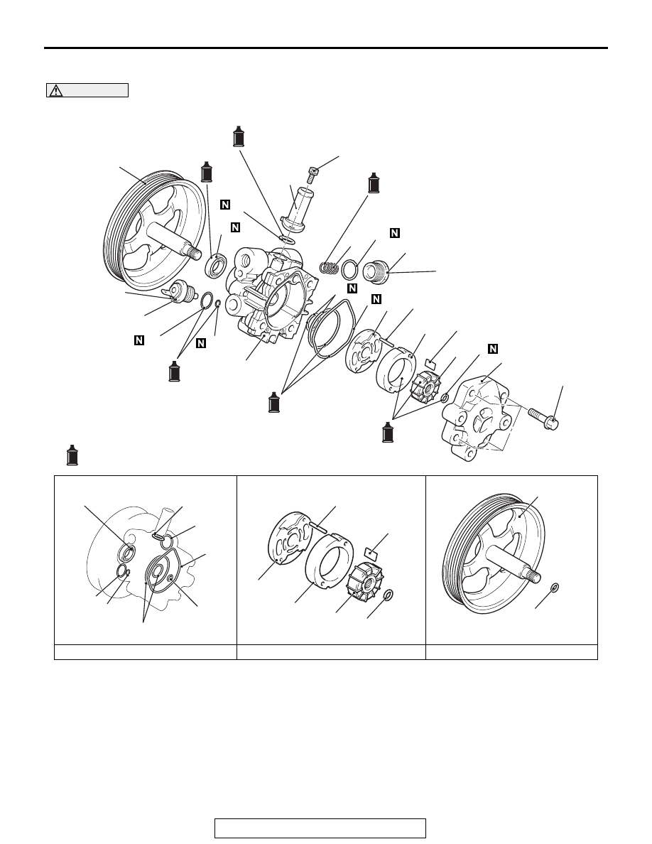
POWER STEERING OIL PUMP ASSEMBLY
TSB Revision
POWER STEERING
37-51
DISASSEMBLY AND ASSEMBLY
M1372005401165
CAUTION
Do not use ATF-SP II M and ATF-SP III for the power steering fluid.
AC505810 AO
4
11
13
16
10
2
9
8
6
5
7
3
1
16
2
11
13
10
3
9
8
6
5
7
3
4
3
15
14
12
Oil pump seal kit
: Genuine MITSUBISHI power steering fluid or ATF DEXRON III or DEXRON II
Oil pump cartridge kit
Oil pump pulley and shaft kit
20
17
18
19
18
19
<2.4L Engine>
28 ± 1 N·m
20.7 ± 0.7 ft-lb
12 ± 1 N·m
106 ± 8 in-lb
28 ± 2 N·m
21 ± 1 ft-lb
59 ± 10 N·m
44 ± 7 ft-lb