Mitsubishi Outlander GS45X. Manual - part 1571


  Index      Mitsubishi     Mitsubishi Outlander GS45X - service repair manual


Search            


Content   ..  1569  1570  1571  1572   ..


Mitsubishi Outlander GS45X. Manual - part 1571


POWER STEERING GEAR BOX AND LINKAGE

TSB Revision

POWER STEERING

37-47

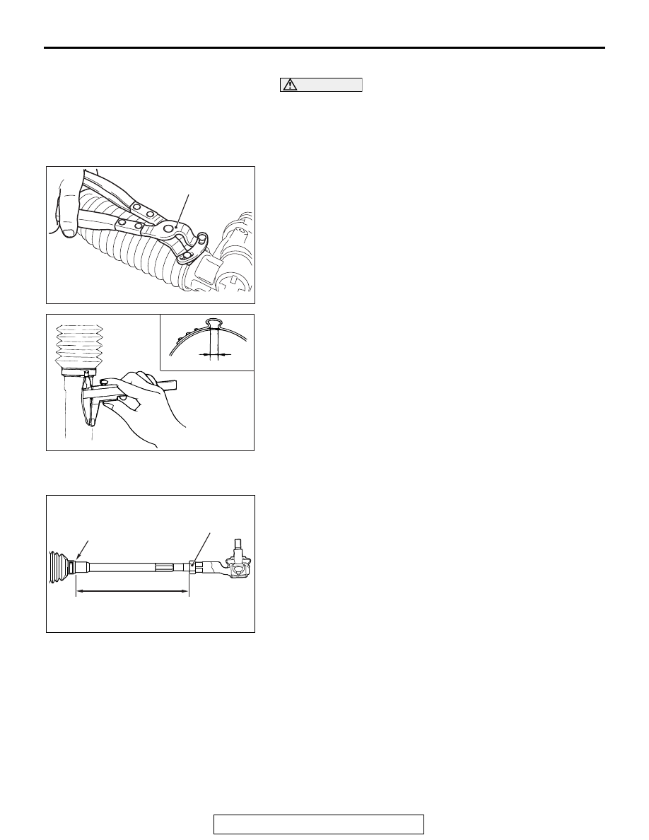
>>B<< BAND INSTALLATION

CAUTION

• Hold the rack housing, and use special tool bellows 

band crimping tool (MB992209) to crimp the bellows 
band securely.

• Crimp the bellows band until special tool (MB992209) 

touches the stopper.

1. Use special tool boot band crimping tool (MB992209) to 

crimp the bellows band.

2. Check that crimped width (A) is within the standard value.

Standard value (A): 2.4 

 2.8 mm

.

>>C<< TIE-ROD END/JAM NUT INSTALLATION

Screw in the tie-rod to the length shown in the figure, and 
hand-tighten the jam nut.
NOTE: Install the steering gear and linkage to the body, adjust 
the toe-in, and then tighten the jam nut to the specified torque.

AC701769

MB992209

AD

ACX01166 AC

A

AC703667

207 mm (8.1 in)

AG

Edge of bellows
assembly

Jam nut

POWER STEERING OIL PUMP ASSEMBLY

TSB Revision

POWER STEERING

37-48

POWER STEERING OIL PUMP ASSEMBLY

REMOVAL AND INSTALLATION

M1372005201978

Pre-removal operation
• Power Steering Fluid Draining (Refer to 

P.37-24

).

• Engine Upper Cover Removal (Refer to GROUP 11A − 

Camshaft 

P.11A-26

 <2.4L>).

• Engine Room Side Cover (RH) Removal (Refer to 

GROUP 51 

− Under Cover 

P.51-22

 <3.0L>).

• Generator and Others Belt Removal (Refer to GROUP 

11A 

− Crankshaft Pulley 

P.11A-21

 <2.4L>, GROUP 11C 

− 

Crankshaft Pulley 

P.11C-23

 <3.0L>).

Post-installation operation
• Generator and Others Belt Installation (Refer to GROUP 

11A

− Crankshaft Pulley 

P.11A-21

 <2.4L>, GROUP 11C 

− 

Crankshaft Pulley 

P.11C-23

 <3.0L>).

• Generator and Others Belt Tension Check (Refer to 

GROUP 11A 

− On-vehicle Service − Drive Belt Tension 

Check 

P.11A-9

 <2.4L>, GROUP 11C 

− On-vehicle Ser-

vice 

− Generator Drive Belt Tension Check 

P.11C-8


<3.0L>). 

• Engine Upper Cover Installation (Refer to GROUP 11A − 

Camshaft 

P.11A-26

 <2.4L>).

• Engine Room Side Cover (RH) Installation (Refer to 

GROUP 51 

− Under Cover 

P.51-22

 <3.0L>).

• Power Steering Fluid Refilling and Bleeding (Refer to 

P.37-25

).

AC711076 AJ

8

5

1

4

6

2

7

N

9

3

57 ± 7 N·m
42 ± 5 ft-lb

13 ± 2 N·m
115 ± 17 in-lb

13 ± 2 N·m
115 ± 17 in-lb

25 ± 4 N·m
18 ± 2 ft-lb

25 ± 4 N·m
18 ± 2 ft-lb

48 ± 7 N·m
35 ± 5 ft-lb

44 ± 8 N·m
32 ± 5 ft-lb

44 ± 10 N·m
33 ± 7 ft-lb

23 ± 2 N·m
17 ± 1 ft-lb

<2.4L Engine>

Removal steps 

>>A<<

1.

Suction hose connection

2.

Pressure switch connector 
connection

3.

Clamp bolt

4.

Eye bolt

5.

Gasket

6.

Pressure hose assembly 
connection 

7.

Harness bracket 

8.

Oil pump assembly

9.

Oil pump bracket

Removal steps (Continued)

POWER STEERING OIL PUMP ASSEMBLY

TSB Revision

POWER STEERING

37-49

REMOVAL SERVICE POINT

.

<<A>> OIL PUMP ASSEMBLY REMOVAL

When removing the oil pump assembly, remove the stabilizer 
link and stabilizer bar bracket, shift the stabilizer bar to the left 
of the vehicle, and then remove the assembly from the front 
wheel house (right side).(Refer to GROUP 33 - Stabilizer Bar 
Removal And Installation 

P.33-20

 .)

AC705772 AF

2

6

7

8

3

4

N

13 ± 2 N·m
115 ± 17 in-lb

25 ± 4 N·m
18 ± 2 ft-lb

57 ± 7 N·m
42 ± 5 ft-lb

50 ± 7 N·m
37 ± 5 ft-lb

1

5

<3.0L Engine>

Removal steps 

1.

Pressure switch connector 
connection

>>A<<

2.

Suction hose connection

3.

Eye bolt

4.

Gasket

5.

Pressure hose assembly 
connection

<<

A

>>

6.

Oil pump assembly

7.

Heat protector

8.

Power steering pump bracket

Removal steps (Continued)

AC703638AB

Oil pump assembly

Stabilizer link

Stabilizer bar

POWER STEERING OIL PUMP ASSEMBLY

TSB Revision

POWER STEERING

37-50

INSTALLATION SERVICE POINT

.

>>A<< SUCTION HOSE CONNECTION

Align the suction hose marking within the area shown in the fig-
ure and connect the suction hose.

INSPECTION

M1372005300466

• Check the drive belt for cracks.

• Check the pulley for uneven rotation.

AC607830

AF

Suction hose

Marking

Oil pump

30˚

<2.4L Engine>

AC707955

AE

<3.0L Engine>

Marking

Oil pump assembly

Suction hose


Content   ..  1569  1570  1571  1572   ..