Mitsubishi Outlander GS45X. Manual - part 1569


  Index      Mitsubishi     Mitsubishi Outlander GS45X - service repair manual


Search            


Content   ..  1567  1568  1569  1570   ..


Mitsubishi Outlander GS45X. Manual - part 1569


STEERING COLUMN SHAFT ASSEMBLY

TSB Revision

POWER STEERING

37-39

DISASSEMBLY SERVICE POINT

.

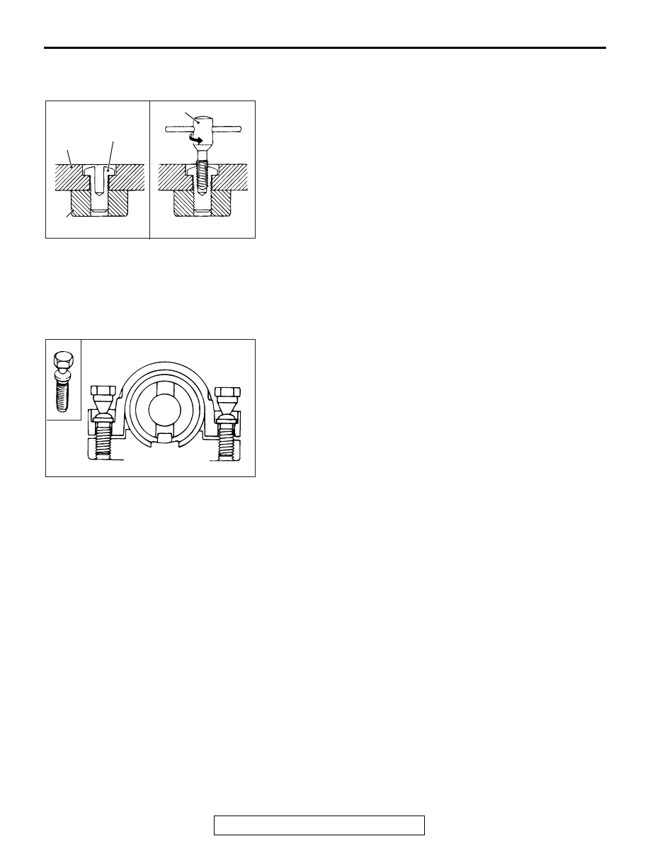
<<A>> STEERING LOCK BOLT REMOVAL

1. Use a drill to make a hole just deeply enough for the tap to 

stand on the steering lock bolt.

2. Use a left-hand thread tap to remove the steering lock bolt.

ASSEMBLY SERVICE POINT

.

>>A<< STEERING LOCK CYLINDER ASSEM-
BLY/STEERING LOCK BRACKET/STEERING 
LOCK BOLT INSTALLATION

1. When installing the steering lock assembly to the steering 

column shaft assembly, temporarily assemble the steering 
lock assembly while aligning it with the boss on the column.

2. Make sure that the steering lock operates normally, and then 

tighten evenly the both steering lock bolt until their head are 
broken off.

AC609628AB

Steering lock
assembly

Steering
lock bolt

Steering lock
assembly

Reverse screw tap

ACX01139 AB

POWER STEERING GEAR BOX AND LINKAGE

TSB Revision

POWER STEERING

37-40

POWER STEERING GEAR BOX AND LINKAGE

REMOVAL AND INSTALLATION

M1372010902006

CAUTION

• Before removing the steering wheel and driver’s airbag module, refer to GROUP 52B  Service 

Precautions and Driver’s Airbag Module and Clock Spring. Position the front wheels in a straight 
ahead direction. If you fail to do this, the clock spring for SRS may be damaged, making the SRS 
(air bag) inoperable which may cause serious injury to the driver.

• The bolts marked with 

*

 are coated with the friction coefficient stabilizer. When removed these 

parts, make sure that they are free of damage, remove any dust and dirt on the bearing surfaces 
and the threads, and tighten to the specified torque.

• After installation, perform a calibration for the ASC-ECU to learn the steering wheel sensor neutral 

point. (Refer to GROUP 35C 

 On-vehicle Service, Steering Wheel Sensor Calibration 

P.35C-283

<Vehicles with ASC>.

Pre-removal operation
• Power Steering Fluid Draining (Refer to 

P.37-24

.)

• Steering Wheel Assembly and Driver’s Air Bag Module 

Removal (Refer to 

P.37-31

.)

• Steering Shaft Cover Removal (Refer to 

P.37-35

.)

• Engine room Under Cover Front (A,B,C), Engine room 

Side Cover, Engine room Under Cover Rear Removal 

(Refer to GROUP 51 

− Under Cover 

P.51-22

.)

• Front Exhaust Pipe Removal (Refer to GROUP 15 − 

Exhaust Pipe And Main Muffler 

P.15-22

 <2.4L>, 

P.15-25


<3.0L>)

• Front Roll Stopper And Centermember Assembly 

Removal (Refer to GROUP 32 

− Engine Roll Stopper and 

Centermember 

P.32-11

.)

Post-installation operation
• Front Roll Stopper And Centermember Assembly Installa-

tion (Refer to GROUP 32 

− Engine Roll Stopper and Cen-

termembe

P.32-11

.)

• Front Exhaust Pipe Installation (Refer to GROUP 15 − 

Exhaust Pipe And Main Muffle

P.15-22

 <2.4L>, 

P.15-25


<3.0L>)

• Engine room Under Cover Front (A,B,C), Engine room 

Side Cover, Engine room Under Cover Rear Installation 

(Refer to GROUP 51 

− Under Cover 

P.51-22

.)

• Using your fingers, press the dust cover of each joint to 

check for a crack or damage.

• Steering Shaft Cover Installation (Refer to 

P.37-35

.)

• Steering Wheel Assembly and Driver’s Air Bag Module 

Installation (Refer to 

P.37-31

.)

• Power Steering Fluid Refilling and Bleeding (Refer to 

P.37-24

.)

• Steering wheel straight-ahead position check

• Wheel Alignment Check and Adjustment (Refer to 

GROUP 33 

− On-vehicle Service − Front Wheel Align-

ment Check and Adjustment 

P.33-8

.)

POWER STEERING GEAR BOX AND LINKAGE

TSB Revision

POWER STEERING

37-41

AC802368 AB

3

6

2

9

7

8

5

1

N

13

N

14

12

4

11

*

7

8

<2.4L Engine>

5.0 ± 2.0 N·m
44 ± 17 in-lb

20 ± 5 N·m
15 ± 3 ft-lb

25 ± 5 N·m
18 ± 3 ft-lb

57 ± 7 N·m
42 ± 5 ft-lb

110 ± 11 N·m
81 ± 8 ft-lb

53 ± 8 N·m

*

39 ± 5 ft-lb

*

50 ± 5 N·m
37 ± 3 ft-lb

70 ± 10 N·m
52 ± 7 ft-lb

110 ± 11 N·m
81 ± 8 ft-lb

53 ± 8 N·m

*

39 ± 5 ft-lb

*

50 ± 5 N·m
37 ± 3 ft-lb

*

10 <AWD>

10 <FWD>

*

*

POWER STEERING GEAR BOX AND LINKAGE

TSB Revision

POWER STEERING

37-42

Required Special Tools:

• MB991897 or MB992011: Ball joint remover

AC709470AE

3

6

2

9

7

8

8

10 <AWD>

5

1

N

13

N

7

10 <FWD>

11

14

12

4

*

110 ± 11 N·m
81 ± 8 ft-lb

110 ± 11 N·m
81 ± 8 ft-lb

*

<3.0L>

5.0 ± 2.0 N·m
44 ± 17 in-lb

20 ± 5 N·m
15 ± 3 ft-lb

25 ± 5 N·m
18 ± 3 ft-lb

57 ± 7 N·m
42 ± 5 ft-lb

70 ± 10 N·m
52 ± 7 ft-lb

53 ± 8 N·m

*

39 ± 5 ft-lb

*

50 ± 5 N·m
37 ± 3 ft-lb

53 ± 8 N·m

*

39 ± 5 ft-lb

*

50 ± 5 N·m
37 ± 3 ft-lb

*

*

Removal steps 

1.

Steering gear and joint 
connecting bolt

<<A>>

2.

Self-lock nut (Tie-rod end and 
knuckle connection)

3.

Eye bolt

4.

Pressure hose connection

5.

Gasket

6.

Return hose connection

7.

Flanged nut

8.

Engine rear roll stopper 
bracket connecting bolt

<<B>>

9.

Front axle crossmember

10. Engine rear roll stopper
11. Heat protector

>>A<<

12. Joint cover grommet
13. Flanged bolt
14. Steering gear and linkage

Removal steps (Continued)


Content   ..  1567  1568  1569  1570   ..