Content .. 1556 1557 1558 1559 ..
Mitsubishi Outlander GS45X. Manual - part 1558
PARKING BRAKE LINING AND DRUM
TSB Revision
PARKING BRAKES
36-17
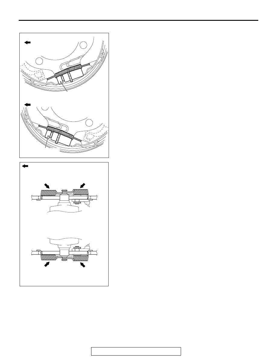
>>C<< ADJUSTER ASSEMBLY INSTALLATION
Install the adjuster assemblies. The shoe adjusting bolt should
be mounted to the rear of the vehicle for the right wheel, and to
the front of the vehicle for the left wheel.
.
>>D<< SHOE-TO-ANCHOR SPRING
INSTALLATION
The shoe-to-anchor springs are not interchangeable because
their spring loads are different. The one with blue paint mark
should be installed to the front of the vehicle, and the other with
yellow paint to the rear of the vehicle, respectively.
AC801849AB
Shoe adjusting bolt
Shoe adjusting bolt
<Right side wheel>
<Left side wheel>
Front of the vehicle
Rear of the vehicle
AC706198 AB
Front of the vehicle
Blue paint
Yellow paint
Blue paint
Yellow paint
<Right side wheel>
<Left side wheel>