Mitsubishi Outlander GS45X. Manual - part 1556


  Index      Mitsubishi     Mitsubishi Outlander GS45X - service repair manual


Search            


Content   ..  1554  1555  1556  1557   ..


Mitsubishi Outlander GS45X. Manual - part 1556


ON-VEHICLE SERVICE

TSB Revision

PARKING BRAKES

36-9

ON-VEHICLE SERVICE

PARKING BRAKE LEVER STROKE CHECK AND 
ADJUSTMENT

M1361000900889

.

STROKE CHECK

Attach the spring scale to the center of the parking brake lever 
grip. Then, check that the stroke is within the standard value 
when the parking brake lever is pulled to the vertical direction of 
the lever with a force of approximately 200 N (45 pounds).

Standard value: 3 to 5 notches

.

STROKE ADJUSTMENT

If the parking brake lever stroke is out of the standard range, 
adjust as described below:
1. Remove the rear floor console assembly (Refer to GROUP 

52A 

− Rear Floor Console Assembly 

P.52A-8

).

2. Loosen the adjusting nut to the end of the cable rod in order 

to allow slack in the cables.

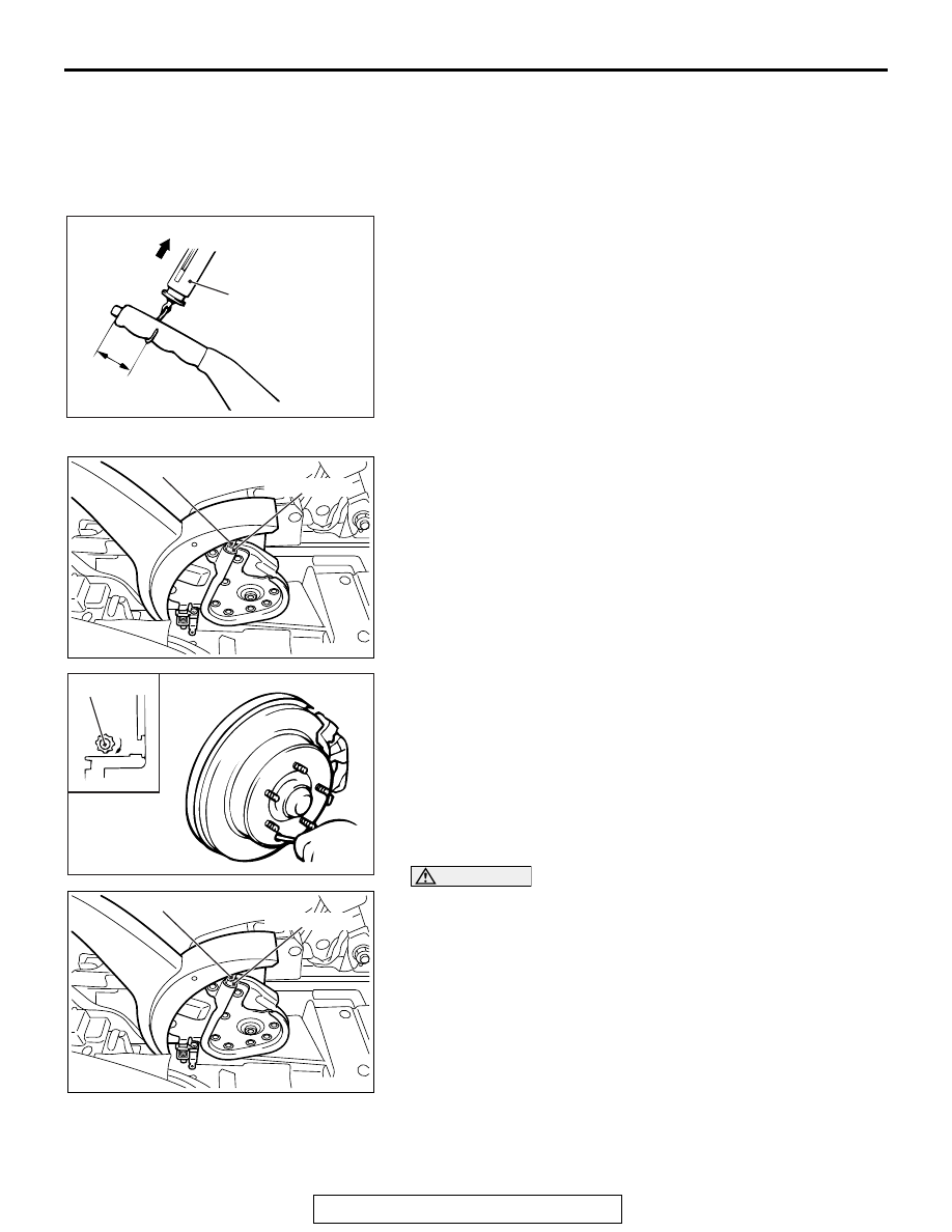
3. Remove the rear brake disc adjusting hole plug. Then insert 

a flat-tipped screwdriver to turn the adjuster to the arrow 
direction (to expand the shoe) until the parking brake shoe 
makes contact and the disc can no longer be turned. Back 
off the adjuster to the opposite direction by five notches.

CAUTION

Be careful that the parking brake lever notch number 
should be within the standard range. If the notch number 
is too low, rear brake dragging can be caused.
4. Adjust the parking brake lever stroke to the standard value 

by turning the adjusting nut. After adjustment, check that 
there is no free play between the adjusting nut and the 
parking brake lever.

5. After the parking brake lever stroke is adjusted, raise the 

rear of the vehicle. Release the parking brake, and turn the 
rear wheels to confirm that the rear brakes are not dragging.

AC604651AD

Spring scale

Pull

Approximately
40 mm (1.57 inch)

AC702713

AB

Cable rod

Adjusting nut

AC702714 AB

Adjuster

AC702713

AB

Cable rod

Adjusting nut

ON-VEHICLE SERVICE

TSB Revision

PARKING BRAKES

36-10

PARKING BRAKE SWITCH CHECK

M1361003301157

CAUTION

Do not apply grease or lubricant to the switch and the 
switch installation section to avoid malfunction of the 
switch. In addition, do not use gloves which have grease 
on them.
1. Remove the rear floor console assembly (Refer to GROUP 

52A 

− Rear Floor Console 

P.52A-8

).

2. Check for continuity between the parking brake switch 

terminal and the switch mounting bolt.

PARKING BRAKE LINING SEATING PROCEDURE

M1361005100101

CAUTION

Perform lining seating in a place with good visibility, and 
pay special attention to safety.
Perform lining seating by the following procedure when replac-
ing the parking brake shoe assemblies or the rear brake discs, 
or when brake performance is insufficient.
1. Adjust the parking brake lever stroke to the standard value 

(Refer to 

P.36-9

).

2. Hook a spring scale onto the center of the parking brake 

lever grip and pull it with a force of 98 

− 147 N (22 − 33 

pounds) in a direction perpendicular to the handle.

3. Drive the vehicle at a constant speed of 35 

− 50 km/h (22 − 

31 mph) for 100 meters (328 feet).

4. Release the parking brake and let the brakes cool for five to 

ten minutes.

5. Repeat the procedure in steps 2. to 4. four to five times.

Check condition

Normal condition

When parking brake 
lever is pulled.

Continuity exists


(2 

Ω or less)

When parking brake 
lever is released.

No continuity

AC702713

AC

AC702715

Pull

AB

Spring scale

Approximately 
40 mm (1.6 in)

PARKING BRAKE LEVER

TSB Revision

PARKING BRAKES

36-11

PARKING BRAKE LEVER

REMOVAL AND INSTALLATION

M1361001300921

CAUTION

Do not apply grease or lubricant to the switch and the switch installation section to avoid malfunction 
of the switch. In addition, do not use gloves which have grease on them.

Pre-removal operation
Rear Floor Console Assembly Removal (Refer to GROUP 
52A 

− Rear Floor Console 

P.52A-8

).

Post-installation operation
• Parking Brake Lever Stroke Check (Refer to 

P.36-9

).

• Rear Floor Console Assembly Installation (Refer to 

GROUP 52A 

− Rear Floor Consol

P.52A-8

).

AC506641

AC704918AD

Section  A – A

Section  B – B

Section  C – C

Section  D – D

A

A

B

B

C

C

D

D

1

2

3

4

20 ± 5 N·m
15 ± 3 ft-lb

20 ± 5 N·m
15 ± 3 ft-lb

5

N

Removal steps 

Release the parking brake lever.

Loosen the adjusting nut.

1.

Parking brake switch connector 
connection

>>

A

<< 2.

Parking brake rear cable assembly 
connection

3.

Parking brake lever assembly

4.

Parking brake switch

5.

Adjusting nut

Removal steps (Continued)

PARKING BRAKE LEVER

TSB Revision

PARKING BRAKES

36-12

INSTALLATION SERVICE POINT

.

>>A<< PARKING BRAKE REAR CABLE ASSEM-
BLY CONNECTION INSTALLATION

CAUTION

Check that the equalizer and the parking brake rear cable 
assembly are connected correctly. If the parking brake is 
applied with the equalizer and the parking brake rear cable 
assembly connected improperly, the equalizer may be 
damaged.
Connect the parking brake rear cable assembly to the equalizer 
as shown in the figure.

AC903102 AF

Equalizer

Equalizer

Parking brake 
rear cable assembly

A

A

Section A - A

Parking brake 
rear cable assembly


Content   ..  1554  1555  1556  1557   ..