Mitsubishi Outlander GS45X. Manual - part 1541


  Index      Mitsubishi     Mitsubishi Outlander GS45X - service repair manual


Search            


Content   ..  1539  1540  1541  1542   ..


Mitsubishi Outlander GS45X. Manual - part 1541


SHOCK ABSORBER ASSEMBLY

TSB Revision

REAR SUSPENSION

34-33

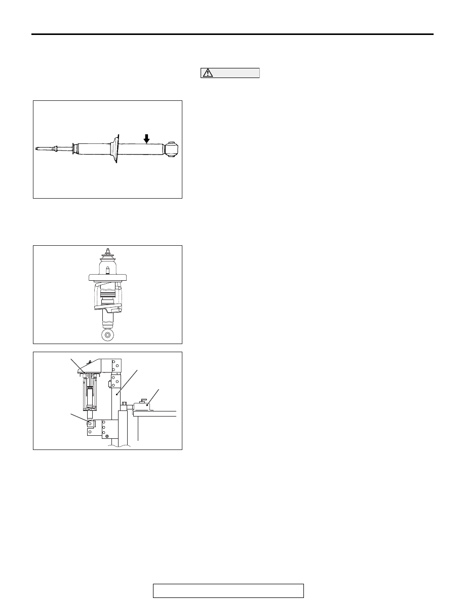
<<B>> SHOCK ABSORBER DISPOSAL 
PROCEDURES

CAUTION

Wear the protective glasses. Although the gas is harmless, 
drilling chips may be blown out by the gas.
Before disposal of the shock absorber, place the shock 
absorber on the level surface with the piston rod extended, and 
make a hole of approximately 3 mm (0.12 in) in diameter at the 
point shown in the figure to discharge the gas.

ASSEMBLY SERVICE POINTS

.

>>A<< COIL SPRING INSTALLATION

1. Install the coil spring end as shown in the figure, so that it 

should face the vehicle rearward.

2. Set the shock absorber to special tools: MB991793, 

MB991796, MB991794 and MB991830, and slowly 
compress the coil spring while guiding the shock absorber 
piston rod through the hole on the upper spring bracket by 
hand:
NOTE: Use the bolts and nuts removed from the vehicle to 
secure the shock absorber assembly and tighten them 
lightly by hand.

.

AC102270 AB

AC508628

AC403179

MB991794

AB

MB991830

MB991796

MB991793

SHOCK ABSORBER ASSEMBLY

TSB Revision

REAR SUSPENSION

34-34

>>B<< SELF-LOCKING NUT INSTALLATION

CAUTION

The locking nut for the piston rod inside the shock 
absorber may be loose. Do not use an impact wrench to 
tighten the self-locking nut.
Counter the piston rod of the shock absorber as shown in the 
figure, and tighten the self-locking nut to the specified torque.

Tightening torque: 25 

± 5 Nm (19 ± 3 ft-lb)

DISASSEMBLY AND ASSEMBLY <2.4L ENGINE: 7 PERSONS SEAT, 3.0L ENGINE>

M1341002700232

AC102268AB

Piston rod

AC608517

25 ± 5 N·m
19 ± 3 ft-lb

3

1

2

9

4

7

5

6

8

N

AC

Disassembly steps 

<<

A

>>

>>

A

<<

1.

Self-locking nut

2.

Washer

3.

Bushing B

4.

Collar

5.

Spring upper bracket assembly

6.

Bushing A

7.

Plate

8.

Bump rubber

9.

Shock absorber

Disassembly steps (Continued)

SHOCK ABSORBER ASSEMBLY

TSB Revision

REAR SUSPENSION

34-35

DISASSEMBLY SERVICE POINT

.

<<A>> SELF-LOCKING NUT REMOVAL

Counter the piston rod of the shock absorber as shown in the 
figure to remove the self-locking nut.

ASSEMBLY SERVICE POINT

.

>>A<< SELF-LOCKING NUT INSTALLATION

CAUTION

The locking nut for the piston rod inside the shock 
absorber may be loose. Do not use an impact wrench to 
tighten the self-locking nut.
Counter the piston rod of the shock absorber as shown in the 
figure, and tighten the self-locking nut to the specified torque.

Tightening torque: 25 

± 5 Nm (19 ± 3 ft-lb)

AC102268

AC708462 AC

Piston rod

AC102268AB

Piston rod

STABILIZER BAR

TSB Revision

REAR SUSPENSION

34-36

STABILIZER BAR

REMOVAL AND INSTALLATION

M1341003000571

<2.4L Engine: 5 persons seat>

<2.4L Engine: 7 persons seat, 3.0L Engine>

AC611124AD

3

2

4

1

39 ± 6 N·m
29 ± 4 ft-lb

31 ± 4 N·m
23 ± 3 ft-lb

39 ± 6 N·m
29 ± 4 ft-lb

AC602797

39 ± 6 N·m
29 ± 4 ft-lb

3

1

2

4

31 ± 4 N·m
23 ± 3 ft-lb

39 ± 6 N·m
29 ± 4 ft-lb

AC

Removal steps 

1.

Stabilizer link

>>

A

<< 2.

Stabilizer bracket

>>

A

<< 3.

Bushing

Rear differential carrier assembly 
(Refer to GROUP 27B, Differential 
carrier assembly 

P.27B-31

.)

>>

A

<< 4.

Stabilizer bar

Removal steps (Continued)


Content   ..  1539  1540  1541  1542   ..