Mitsubishi Outlander GS45X. Manual - part 1542


  Index      Mitsubishi     Mitsubishi Outlander GS45X - service repair manual


Search            


Content   ..  1540  1541  1542  1543   ..


Mitsubishi Outlander GS45X. Manual - part 1542


STABILIZER BAR

TSB Revision

REAR SUSPENSION

34-37

INSTALLATION SERVICE POINT

.

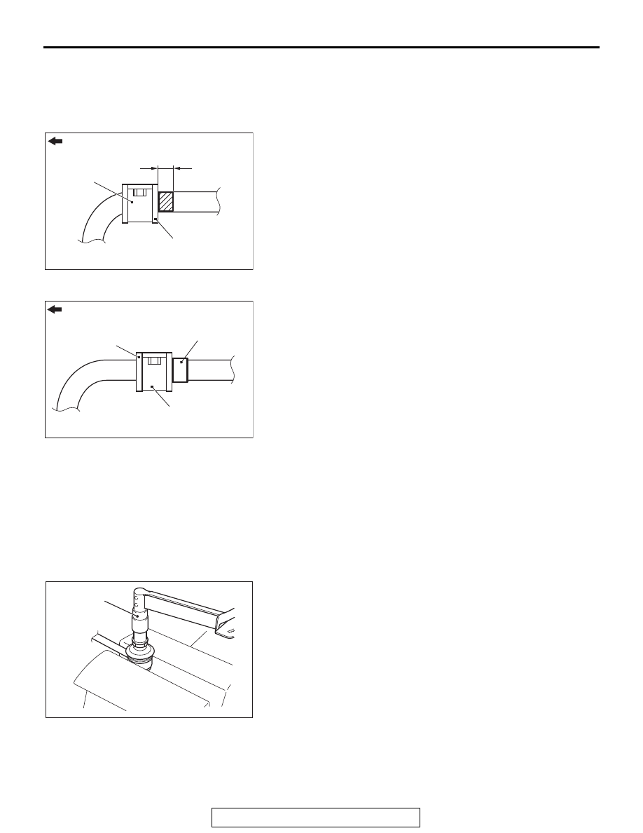
>>A<< STABILIZER BAR/BUSHING/STABILIZER 
BRACKET INSTALLATION

<2.4L Engine: 5 persons seat>
Position the identification mark of the stabilizer bar at the left 
side of the vehicle as shown in the figure, and tighten the stabi-
lizer bracket mounting nut.

<2.4L Engine: 7 persons seat, 3.0L Engine>
Install the stabilizer bracket as shown in the figure, and tighten 
the stabilizer bracket mounting nut.

INSPECTION

M1341001400551

• Check the bushings for wear and deterioration.

• Check the stabilizer bar for deterioration or damage.

• Check all bolts for condition and straightness.

STABILIZER LINK BALL JOINT ROTATION 
TORQUE CHECK

M1341019300043

1. Move the stabilizer link ball joint stud back and forth for 

several times, install the stud with nut, and measure the 
stabilizer link ball joint rotation torque using the preload 
socket (Special tool: MB990326).

Standard value: 0.5 

 2.9 Nm (4.4  25.7 in-lb)

2. When the measured value exceeds the standard range, 

replace the stabilizer link.

3. When the measured value is lower than the standard value, 

check the stabilizer link ball joint that there is no looseness 
or gritty feeling. If there is no looseness or gritty feeling, it is 
judged as usable.

AC507099AB

Outside of the vehicle

Approx.10 mm (0.39 in)

Bushing

Stabilizer bracket

AC608491AD

Outside of the vehicle

Bushing

Stabilizer clamp

Stopper ring

AC404845

MB990326

AC

REAR SUSPENSION CROSSMEMBER

TSB Revision

REAR SUSPENSION

34-38

STABILIZER LINK BALL JOINT COVER CHECK

M1341019100049

1. Using your fingers, press the dust cover to check for a crack 

or damage.

2. If the dust cover has a crack or damage, replace the 

stabilizer link.
NOTE: If the dust cover has a crack or damage, the ball joint 
could be damaged. If the dust cover is damaged during 
maintenance, replace it.

REAR SUSPENSION CROSSMEMBER

REMOVAL AND INSTALLATION

M1341006800985

CAUTION

• The parts indicated by * are the bolts with friction coefficient stabilizer. In removal, ensure there is 

no damage, clean dust and soiling from the bearing and thread surfaces, and tighten them to the 
specified torque.

Pre-removal operation
• Control link arm removal (Refer to 

P.34-12

.)

• Upper arm removal (Refer to 

P.34-12

.)

• Rear suspension stabilizer bar removal (Refer to 

P.34-36

.)

• Center exhaust pipe removal (Refer to GROUP 15 − 

Exhaust Pipe and Muffler <4B1>

P.15-22

, <6B3> 

P.15-25

.)

• Driveshaft removal (Refer to GROUP 27B − Driveshaft 

Assembly 

P.27B-24

.)

• Rear differential assembly removal (Refer to GROUP 27B 

−Differential Carrier Assembly 

P.27B-31

.)

Post-installation operation
• Rear differential assembly installation (Refer to GROUP 

27B 

−Differential Carrier Assembly 

P.27B-31

.)

• Driveshaft installation (Refer to GROUP 27B − Driveshaft 

Assembly 

P.27B-24

.)

• Center exhaust pipe installation (Refer to GROUP 15 − 

Exhaust Pipe and Muffler <4B1>

P.15-22

, <6B3>

P.15-25

.)

• Rear suspension stabilizer bar installation (Refer to 

P.34-36

.)

• Upper arm installation (Refer to 

P.34-12

.)

• Control link installation (Refer to 

P.34-12

.)

• Rear wheel alignment check and adjustment (Refer to 

P.34-10

.)

AC800069AE

2

1

*

*

*

*

3

2

11 ± 2 N·m
98 ± 17 in-lb

71 ± 10 N·m
52 ± 7 ft-lb

11 ± 3 N·m
97 ± 26 in-lb

71 ± 10 N·m
52 ± 7 ft-lb

71 ± 10 N·m
52 ± 7 ft-lb

71 ± 10 N·m
52 ± 7 ft-lb

11 ± 3 N·m
97 ± 26 in-lb

<FWD>

*

*

*

*

REAR SUSPENSION CROSSMEMBER

TSB Revision

REAR SUSPENSION

34-39

REMOVAL SERVICE POINT

.

<<A>> REAR SUSPENSION CROSSMEMBER 
REMOVAL <2.4 L ENGINE: 5 PERSONS SEAT>

To avoid the break hose load, fix the trailing arm assembly with 
a rope as shown in the figure.

AC800070

<AWD>

AE

2

1

*

*

*

*

3

2

11 ± 2 N·m
98 ± 17 in-lb

71 ± 10 N·m
52 ± 7 ft-lb

11 ± 3 N·m
97 ± 26 in-lb

71 ± 10 N·m
52 ± 7 ft-lb

71 ± 10 N·m
52 ± 7 ft-lb

71 ± 10 N·m
52 ± 7 ft-lb

*

*

*

*

11 ± 3 N·m
97 ± 26 in-lb

Removal steps 

1.

Rear wheel speed sensor clamp

2.

Rear suspension crossmember 
stay

<<

A

>>

3.

Rear suspension crossmember

Removal steps (Continued)

AC507199

AB

Rope

NOTES


Content   ..  1540  1541  1542  1543   ..