Content .. 1533 1534 1535 1536 ..
Mitsubishi Outlander GS45X. Manual - part 1535
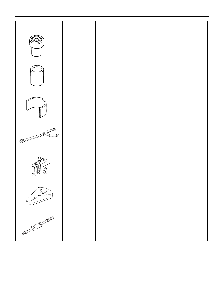
SPECIAL TOOLS
TSB Revision
REAR SUSPENSION
34-9
MB992123
Arm bushing
remover and
installer
−
Lower arm bushing removal and press-fit
MB991448
Bushing remover
and installer
base
MB991448-01
MB991449
Bushing remover
and installer
supporter
−
MB990767
Front hub and
flange yoke
holder
MB990767-01
Fixing of the hub
MB990241
Axle shaft puller
A: MB990242
Puller shaft
B: MB990244
Puller bar
MB990241-01 or
General service
tool
Rear hub assembly removal
MB991354
Puller body
General service
tool
MB990211
Slide hammer
General service
tool
Tool
Tool number
and name
Supersession
Application
MB991447
B990767
MB990241AD
MB991354
MB990211