Content .. 1518 1519 1520 1521 ..
Mitsubishi Outlander GS45X. Manual - part 1520
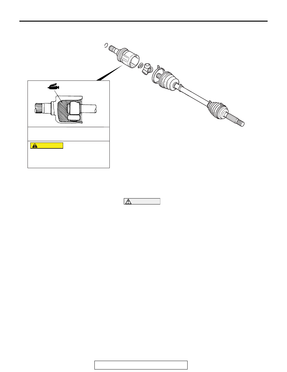
DRIVESHAFT ASSEMBLY
TSB Revision
REAR AXLE <AWD>
27B-29
LUBRICATION POINT
DISASSEMBLY SERVICE POINTS
.
<<A>> ETJ CASE/SPIDER ASSEMBLY REMOVAL
CAUTION
Do not disassemble the spider assembly.
1. Wipe off the grease inside the ETJ case and on the spider
assembly.
2. If the grease is contaminated with the foreign material
(water, dust, etc.), be sure to wash the spider assembly.
.
<<B>> ETJ BOOT REMOVAL
1. Wipe off the grease on the shaft spline.
2. If the ETJ boot is reused, protect the shaft spline area with
taping from the damage in removal of the boot.
AC703495 AB
75 – 10 g (2.6 – 0.3 oz)
Grease: Repair kit grease
amount used:
The drive shaft joint uses special
grease. Do not mix old and new or
different types of grease.
CAUTION