Mitsubishi Outlander GS45X. Manual - part 1518


  Index      Mitsubishi     Mitsubishi Outlander GS45X - service repair manual


Search            


Content   ..  1516  1517  1518  1519   ..


Mitsubishi Outlander GS45X. Manual - part 1518


REAR AXLE HUB ASSEMBLY

TSB Revision

REAR AXLE <AWD>

27B-21

REMOVAL SERVICE POINTS

.

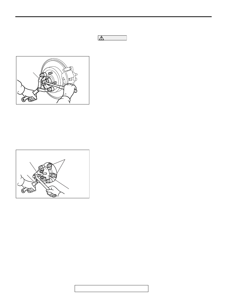
<<A>> DRIVESHAFT NUT REMOVAL

CAUTION

Do not apply the vehicle weight on the rear wheel hub 
assembly with the driveshaft nut loosened. Otherwise, the 
wheel bearing will be broken.
Use special tool MB990767 to fix the hub and remove the 
driveshaft nut.

.

<<B>> CALIPER ASSEMBLY REMOVAL

1. Remove the caliper assembly with brake hose.
2. Secure the removed caliper assembly with a wire or other 

similar material at a position where it will not interfere with 
the removal and installation of the rear wheel hub assembly.

.

<<C>> REAR WHEEL HUB ASSEMBLY REMOVAL

1. If the rear wheel hub assembly is seized with the rear 

driveshaft assembly, use special tools MB990242 and 
MB990244, MB991354 and MB990767 to push the rear 
driveshaft assembly out from the hub and then remove the 
rear wheel hub assembly.

AC703485 AB

MB990767

AC708477

MB991354

MB990244
(MB990241)

MB990242
(MB990241)

AC

MB990767

(Three)

REAR AXLE HUB ASSEMBLY

TSB Revision

REAR AXLE <AWD>

27B-22

2. If the rear wheel hub assembly is seized with the knuckle, 

use special tools MB990211 and MB990241 {combination 
(A)}, or MB990211 and MB991354 {combination (B)} to 
remove the rear wheel hub assembly.

INSTALLATION SERVICE POINTS

.

>>A<< WASHER/DRIVESHAFT NUT INSTALLA-
TION

CAUTION

• The magnetic encoder collects metallic particles easily, 

because it is magnetized. Make sure that the magnetic 
encoder does not collect metallic particles. Check that 
there is not any trouble prior to reassembling it.

• When installing the drive shaft, make sure that it does 

not contact with the magnetic encoder (integrated with 
the inner oil seal) to avoid damage.

• Do not apply the vehicle weight on the rear wheel hub 

assembly before fully tightening the driveshaft nuts. 
Otherwise, the wheel bearing will be broken.

1. Incorporate the driveshaft washer as shown in the figure.
2. Use special tool MB990767 to tighten the driveshaft nuts. At 

this time, tighten the nuts within the specified torque range 
considering the final tightening.

Tightening torque: 144 

 176 Nm (107  129 ft-lb)

3. If the pin holes do not align with the pins, tighten the 

driveshaft nut [less than 200 N

⋅m (147 ft-lb)] and find the 

nearest hole then bend the split ping to fit it.

AC701415 AC

MB990241

MB990211

Combination (A)

AC706385 AB

MB991354

MB990211

Combination (B)

AC703486 AB

Magnetic 
encoder

Wheel 
bearing

Rear wheel
hub assembly

AC703487AB

MB990767

Washer

REAR AXLE HUB ASSEMBLY

TSB Revision

REAR AXLE <AWD>

27B-23

INSPECTION

M1271002100430

HUB ROTATION STARTING TORQUE AND WHEEL 
BEARING END PLAY CHECK

Required Special Tools:

• MB990326: Preload Socket

• MB990998: Front Hub Remover and Installer

• MB991000: Spacer

1. Tighten special tools MB990998 and MB991000 to the 

specified torque.

Tightening torque: 144 

 176 Nm (107  129 ft-lb)

2. Fix the hub in a vice using a piece of wood or the like.
3. Rotate the rear hub in order to seat the bearing.

4. Use special tool MB990326 to measure the hub rotation 

starting torque.

Limit value: 1.4 N

m (1.03 ft-lb)

5. If the hub rotation starting torque at the specified tightening 

torque [144 

− 176 N⋅m (107 − 129 ft-lb)] exceeds the limit 

value, replace the hub.  If there are rough or gritty feelings in 
rotation, replace the hub.

6. Set a dial gauge, and move the hub in the axial direction to 

measure the wheel bearing end play.

Limit: 0.05 mm (0.002 inch)

7. If the wheel bearing end play at the specified tightening 

torque [144 

− 176 N⋅m (107 − 129 ft-lb)] exceeds the limit 

value, replace the hub.

AC703488AB

MB991000

MB990998

AC703489AB

MB990326

Wooden 
block

Wooden 
block

AC703490AB

MB990998

Wooden 
block

Wooden 
block

DRIVESHAFT ASSEMBLY

TSB Revision

REAR AXLE <AWD>

27B-24

DRIVESHAFT ASSEMBLY

REMOVAL AND INSTALLATION

M1271003300675

CAUTION

When removing and installing the rear wheel speed sensor, make sure that its sensor head does not 
contact with surrounding parts to avoid damage.

Pre-installation Operation
• Differential Gear Oil Draining 

• Disconnect joints between Lower Arm, Trailing Arm, 

Shock Absorber, and Stabilizer Link. (Refer to GROUP 34 

− Control Link, Upper Arm, Lower Arm Removal and 

Installation 

P.34-12

.)

• Disconnect joint between Upper Arm and Trailing Arm. 

(Refer to GROUP 34

− Control Link, Upper Arm, Lower 

Arm Removal and Installation 

P.34-12

.)

Post-installation Operation
• Connect Upper Arm and Trailing arm. (Refer to GROUP 

34 

− Control Link, Upper Arm, Lower Arm Removal and 

Installation 

P.34-12

.)

• Connect Lower Arm, Trailing Arm, Shock Absorber, and 

Stabilizer Link. (Refer to GROUP 34 

− Control Link, Upper 

Arm, Lower Arm Removal and Installation 

P.34-12

.)

• Differential Gear Oil Filling (Refer to 

P.27B-16

.)

• Rear Wheel Alignment Check and Adjustment (Refer to 

GROUP 34, On-vehicle Service-Rear Wheel Alignment 

Check and Adjustment 

P.34-10

.)

AC704475

N

AC

N

3

1

2

4

5

6

7

8.5 ± 1.5 N·m
76 ± 13 in-lb

11 ± 2 N·m
98 ± 17 in-lb

144   176 N·m

107   129 ft-lb

<2.4L Engine:
5 persons seat>

N


Content   ..  1516  1517  1518  1519   ..