Mitsubishi Outlander GS45X. Manual - part 1450


  Index      Mitsubishi     Mitsubishi Outlander GS45X - service repair manual


Search            


Content   ..  1448  1449  1450  1451   ..


Mitsubishi Outlander GS45X. Manual - part 1450


SRS AIR BAG DIAGNOSIS

TSB Revision

SUPPLEMENTAL RESTRAINT SYSTEM (SRS)

52B-295

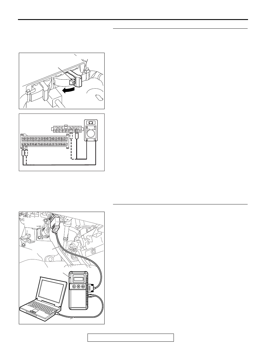
STEP 8. Check the harness for open circuit between 
SRS-ECU connector C-27 (terminal No.61 and 62) and the 
ETACS-ECU connector C-313 (terminal No.4 and 2).
(1) Disconnect the negative battery terminal.
(2) While pushing the part "A" indicated in the figure of the 

harness side connector, turn the lock lever to the direction 
of the arrow to release the lock lever, and disconnect the 
C-27 SRS-ECU connector.

(3) Disconnect the ETACS-ECU connector C-313.

(4) Check for continuity between the following terminals. It 

should be less than 2 ohms.

<Fuse No.12>

• SRS-ECU connector C-27 (terminal No.62) and the 

ETACS-ECU connector C-313 (terminal No.2)

<Fuse No.18>

• SRS-ECU connector C-27 (terminal No.61) and the 

ETACS-ECU connector C-313 (terminal No.4)

Q: Does continuity exist?

YES : Replace the ETACS-ECU (Refer to GROUP 54A, 

ETACS-ECU 

P.54A-826

).

NO :  Repair the harness wire between SRS-ECU 

connector C-27 and the ETACS-ECU connector 
C-313.

STEP 9. Recheck for diagnostic trouble code.
Check again if the DTC is set.
(1) Erase the DTC.
(2) Turn the ignition switch to the "ON" position.
(3) Check if the DTC is set.
(4) Turn the ignition switch to the "LOCK" (OFF) position.
Q: Is DTC B212C <Fuse No.12 circuit> or B212D <Fuse 

No.18 circuit> set?
YES : 
Replace the SRS-ECU (Refer to 

P.52B-436

).

NO :  There is an intermittent malfunction such as poor 

engaged connector(s) or open circuit (Refer to 
GROUP 00, How to Cope with Intermittent 
Malfunction 

P.00-15

).

AC507645

A

AB

Lock lever

AC608812DO

C-27 Harness 
side connector 
(front view)

C-313 Harness side 

connector (front view)

ZC501967

AC404789

AC701411AB

MB991824

MB991827

MB991910

Data link 
connector

SRS AIR BAG DIAGNOSIS

TSB Revision

SUPPLEMENTAL RESTRAINT SYSTEM (SRS)

52B-296

DTC B2207: Occupant Restraint Controller Internal 1


DTC B2208: Occupant Restraint Controller Internal 2


DTC B2209: Occupant Restraint Controller Internal 3


DTC B220A: Occupant Restraint Controller Internal 4


DTC B220B: Occupant Restraint Controller Firing Stored Energy


DTC B220C: Occupant Restraint Controller Accelerometer 1


DTC B220D: Occupant Restraint Controller Accelerometer 2

CAUTION

 If DTCs are set in the SRS-ECU, always diagnose 
the CAN main bus line.

.

DTC SET CONDITION

The above DTC is set if an abnormality is detected in the circuit 
inside the SRS-ECU.

.

TROUBLESHOOTING HINTS

Malfunction of the SRS-ECU

DIAGNOSIS

Required Special Tools:

•  MB991958: Scan Tool (M.U.T.-III Sub Assembly)

• MB991824: Vehicle Communication Interface (V.C.I.)

• MB991827: M.U.T.-III USB Cable

• MB991910: M.U.T.-III Main Harness A (Vehicles with 

CAN communication system)

STEP 1. Using scan tool MB991958, diagnose the CAN bus 
line

CAUTION

To prevent damage to scan tool MB991958, always turn the 
ignition switch to the "LOCK" (OFF) position before con-
necting or disconnecting scan tool MB991958.
(1) Connect scan tool MB991958. Refer to "How to connect the 

scan tool 

P.52B-28

."

(2) Turn the ignition switch to the "ON" position.
(3) Diagnose the CAN bus line.
(4) Turn the ignition switch to the "LOCK" (OFF) position.
Q: Is the CAN bus line found to be normal?

YES : Go to Step 2.
NO :  Repair the CAN bus line (Refer to GROUP 54C, 

Diagnosis 

P.54C-17

).

ZC501967

AC404789

AC701411AB

MB991824

MB991827

MB991910

Data link 
connector

SRS AIR BAG DIAGNOSIS

TSB Revision

SUPPLEMENTAL RESTRAINT SYSTEM (SRS)

52B-297

STEP 2. Recheck for diagnostic trouble code.
Check again if the DTC is set.
(1) Turn the ignition switch to the "ON" position.
(2) Check if the DTC is set.
(3) Turn the ignition switch to the "LOCK" (OFF) position.
Q: Are any "Stored" or "Active" DTCs set?

YES : Replace the SRS-ECU (Refer to 

P.52B-436

).

NO :  There is an intermittent malfunction such as poor 

engaged connector(s) or open circuit (Refer to 
GROUP 00, How to Cope with Intermittent 
Malfunction 

P.00-15

).

DTC B223D: OCM (occupant classification-ECU) DTC Present

CAUTION

If DTC B223D is set in the SRS-ECU, always diag-
nose the CAN main bus line.

.

DTC SET CONDITION

It is set if a DTC occurs in the occupant classifica-
tion-ECU.

.

TROUBLESHOOTING HINTS

• Malfunction of the SRS-ECU

• Malfunction of the occupant classification-ECU

DIAGNOSIS

Required Special Tool:

•  MB991958: Scan Tool (M.U.T.-III Sub Assembly)

• MB991824: Vehicle Communication Interface (V.C.I.)

• MB991827: M.U.T.-III USB Cable

• MB991910: M.U.T.-III Main Harness A (Vehicles with 

CAN communication system)

SRS AIR BAG DIAGNOSIS

TSB Revision

SUPPLEMENTAL RESTRAINT SYSTEM (SRS)

52B-298

STEP 1. Using scan tool MB991958, diagnose the CAN bus 
line.

CAUTION

To prevent damage to scan tool MB991958, always turn the 
ignition switch to the "LOCK" (OFF) position before con-
necting or disconnecting scan tool MB991958.
(1) Connect scan tool MB991958. Refer to "How to connect the 

scan tool 

P.52B-28

."

(2) Turn the ignition switch to the "ON" position.
(3) Diagnose the CAN bus line.
(4) Turn the ignition switch to the "LOCK" (OFF) position.
Q: Is the CAN bus line found to be normal?

YES : Go to Step 2.
NO :  Repair the CAN bus line. (Refer to GROUP 54C, 

Diagnosis 

P.54C-17

).

STEP 2. Recheck for diagnostic trouble code.
Check that the DTC is set in the occupant classification-ECU.
Q: Is the DTC set?

YES : Diagnose the occupant classification-ECU (Refer to 

P.52B-344

).

NO :  Go to Step 3

ZC501967

AC404789

AC701411AB

MB991824

MB991827

MB991910

Data link 
connector


Content   ..  1448  1449  1450  1451   ..