Mitsubishi Outlander GS45X. Manual - part 143


  Index      Mitsubishi     Mitsubishi Outlander GS45X - service repair manual


Search            


Content   ..  141  142  143  144   ..


Mitsubishi Outlander GS45X. Manual - part 143


STEERING WHEEL AUDIO REMOTE CONTROL SWITCH

TSB Revision

CHASSIS ELECTRICAL

54A-569

.

TECHNICAL DESCRIPTION (COMMENT)

The power supply circuit to the steering wheel audio 
remote control switch, the multivision display, or the 
clock spring may be defective.

.

TROUBLESHOOTING HINTS

• Malfunction of steering wheel audio remote con-

trol switch

• Malfunctions of multivision display

• Malfunction of the clock spring

• Damaged harness wires and connectors

DIAGNOSIS

Required Special Tools:

• MB991223: Harness Set

• MB992006: Extra Fine Probe

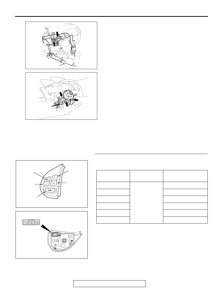
STEP 1. Check the remote controlled radio switch.
Remove the remote controlled radio switch. Then check conti-
nuity between the switch terminals.

Q: Is the remote controlled radio switch in good condition?

YES : Go to Step 2.
NO :  Replace the steering wheel audio remote control 

switch.

AC709494

AG

Connectors: C-07, C-17

C-07 (GR)

C-17

AC900844

Connectors: C-202, C-204, C-213

AW

C-213 (R)

C-202

C-204

Switch Position Tester 

Connection

Measurement Value

No push

− 4

Approximately 71 k

Ω

Mode

Approximately 270 

Ω

CH up

Approximately 740 

Ω

CH down

Approximately 1.3 k

Ω

VOL up

Approximately 2.1 k

Ω

VOL down

Approximately 3.1 k

Ω

AC703778 AB

“VOL up” switch

“CH up” 
switch

“CH down” 
switch

“VOL down” 
switch

“Mode” switch

AC703779 AB

STEERING WHEEL AUDIO REMOTE CONTROL SWITCH

TSB Revision

CHASSIS ELECTRICAL

54A-570

STEP 2. Check clock spring connector C-202 and C-204 for 
loose, corroded or damaged terminals, or terminals 
pushed back in the connector.
Q: Are clock spring connector C-202 and C-204 in good 

condition?
YES : 
Go to Step 3.
NO :  Repair or replace the damaged component(s). Refer 

to GROUP 00E, Harness Connector Inspection 

P.00E-2

. The steering wheel audio remote control 

switch should work normally.

STEP 3. Check the clock spring.
Check whether the clock spring is in good condition. Refer to 
GROUP 52B, Air bag module and clock spring 

P.52B-447

.

Q: Is the check result normal?

YES : Go to Step 4.
NO :  Replace the clock spring.

STEP 4. Check multivision display connector C-07 for 
loose, corroded or damaged terminals, or terminals 
pushed back in the connector.
Q: Is multivision display connector C-07 in good 

condition?
YES : 
Go to Step 5.
NO :  Repair or replace the damaged component(s). Refer 

to GROUP 00E, Harness Connector Inspection 

P.00E-2

. The steering wheel audio remote control 

switch should work normally.

STEP 5. Check the wiring harness between multivision 
display connector C-07 (terminal 53, 69) and clock spring 
connector C-204 (terminal 2, 3).
NOTE: Also check intermediate connector C-17 for loose, cor-
roded, or damaged terminals, or terminals pushed back in the 
connector. If intermediate connector C-17 is damaged, repair or 
replace the connector as described in GROUP 00E, Harness 
Connector Inspection 

P.00E-2

.

• Check the communication lines for open and short circuit.

Q: Is the wiring harness between multivision display 

connector C-07 (terminal 53, 69) and clock spring 
connector C-204 (terminal 2, 3) in good condition?
YES : 
Go to Step 6.
NO :  The wiring harness may be damaged or the 

connector(s) may have loose, corroded or damaged 
terminals, or terminals pushed back in the connector. 
Repair the wiring harness as necessary.

STEERING WHEEL AUDIO REMOTE CONTROL SWITCH

TSB Revision

CHASSIS ELECTRICAL

54A-571

STEP 6. Check steering wheel audio remote control switch 
connector C-213 for loose, corroded or damaged 
terminals, or terminals pushed back in the connector.
Q: Is steering wheel audio remote control switch 

connector C-213 in good condition?
YES : 
Go to Step 7.
NO :  Repair or replace the damaged component(s). Refer 

to GROUP 00E, Harness Connector Inspection 

P.00E-2

. The steering wheel audio remote control 

switch should work normally.

STEP 7. Check the wiring harness between steering wheel 
audio remote control switch connector C-213 (terminal 2, 
4) and clock spring connector C-202 (terminal 5, 4).

• Check the communication lines for open and short circuit.

Q: Is the wiring harness between steering wheel audio 

remote control switch connector C-213 (terminal 2, 4) 
and clock spring connector C-202 (terminal 5, 4) in good 
condition?
YES : 
Go to Step 8.
NO :  The wiring harness may be damaged or the 

connector(s) may have loose, corroded or damaged 
terminals, or terminals pushed back in the connector. 
Repair the wiring harness as necessary.

STEP 8. Retest the system
Check whether you can operate the multivision display by 
using the steering wheel audio remote control switch.
Q: Is the check result normal?

YES : The trouble can be an intermittent malfunction (Refer 

to GROUP 00, How to use 
Troubleshooting/inspection Service Points, How to 
Cope with Intermittent Malfunction 

P.00-15

).

NO :  Replace the multivision display.

STEERING WHEEL AUDIO REMOTE CONTROL SWITCH

TSB Revision

CHASSIS ELECTRICAL

54A-572

Inspection Procedure 3: The illumination of the steering wheel audio remote control switch does not 
come on.

CAUTION

Before replacing the radio and CD player or 
steering wheel audio remote control switch, 
ensure that the power supply circuit, the ground 
circuit and the communication circuit are normal.

.

Steering Audio Switch Illumination Circuit

CLOCK 
SPRING

STEERING 
WHEEL 
AUDIO 
REMOTE 
CONTROL 
SWITCH

INTERFACE 
CIRCUIT

COMBINATION 
METER

ACA02653AC

Connector: C-03

AC900844

Connectors: C-202, C-204, C-213

AW

C-213 (R)

C-202

C-204


Content   ..  141  142  143  144   ..