Mitsubishi Outlander GS45X. Manual - part 1417


  Index      Mitsubishi     Mitsubishi Outlander GS45X - service repair manual


Search            


Content   ..  1415  1416  1417  1418   ..


Mitsubishi Outlander GS45X. Manual - part 1417


SRS AIR BAG DIAGNOSIS

TSB Revision

SUPPLEMENTAL RESTRAINT SYSTEM (SRS)

52B-163

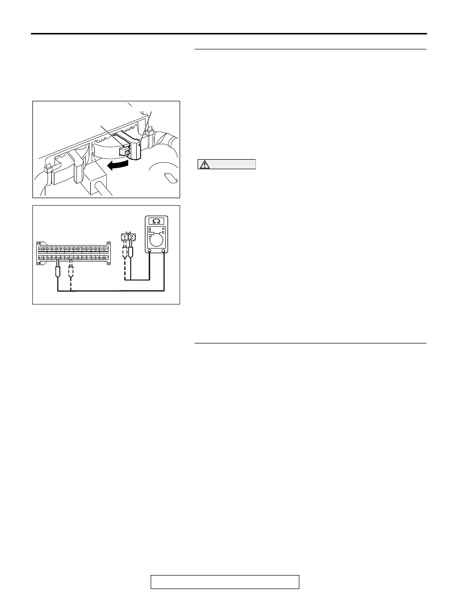
STEP 5. Check the harness wires between SRS-ECU 
connector C-27 (terminal No.55 and 58) and the 
passenger’s seat belt buckle switch connector D-32 
(terminal No.1 and 2).
(1) Disconnect the negative battery terminal.
(2) While pushing the part "A" indicated in the figure of the 

harness side connector, turn the lock lever to the direction 
of the arrow to release the lock lever, and disconnect the 
C-27 SRS-ECU connector.

(3) Disconnect the passenger’s seat belt buckle switch 

connector D-32.

CAUTION

Do not insert a probe into the terminal from D-32 harness 
side connector front side directly, as the connector contact 
pressure may be weakened.

(4) Check for continuity between the following terminals. It 

should be less than 2 ohms <No.B1B56>.

• SRS-ECU connector C-27 (terminal No.55) and the pas-

senger’s seat belt buckle switch connector D-32 (termi-
nal No.1)

• SRS-ECU connector C-27 (terminal No.58) and the pas-

senger’s seat belt buckle switch connector D-32 (termi-
nal No.2)

Q: Is the check result normal?

YES : go to Step 6.
NO :  Repair harness wires between SRS-ECU connector 

C-27 and the passenger’s seat belt buckle switch 
connector D-32.

STEP 6. The passenger’s seat belt buckle switch check. 
Refer to GROUP 52A, Front Seat Belt 

P.52A-40

Q: Is the check result normal?

YES : Go to Step 7.
NO :  Replace the passenger’s seat belt buckle switch.

AC507645

A

AC

Lock lever

AC608812

D-32 Harness side 
connector 
(rear view)

HS

C-27 Harness side 
connector (front view)

SRS AIR BAG DIAGNOSIS

TSB Revision

SUPPLEMENTAL RESTRAINT SYSTEM (SRS)

52B-164

STEP 7. Recheck for diagnostic trouble code. 
Check again if the DTC is set.
(1) Erase the DTC.
(2) Turn the ignition switch to the "ON" position.
(3) Check if the DTC is set.
(4) Turn the ignition switch to the "LOCK" (OFF) position.
Q: Is DTC B1B54, B1B55 or B1B56 set?

YES : Replace the SRS-ECU (Refer to 

P.52B-436

).

NO :  The procedure is complete.

DTC B1B70: Malfunction of G-sensor inside Front Impact Sensor (LH)


DTC B1B71: Malfunction of G-sensor inside Front Impact Sensor (RH)

CAUTION

If DTC B1B70 or B1B71 is set in the SRS-ECU, 
always diagnose the CAN main bus line.

.

DTC SET CONDITIONS

These DTCs are set if the following conditions are 
detected from the analog G-sensor inside the front 
impact sensor output:

• Analog G-sensor is not operating.

• Analog G-sensor characteristics are abnormal.

• Analog G-sensor output is abnormal.

.

TROUBLESHOOTING HINTS

Malfunction of front impact sensor (LH) (for DTC 
B1B70) and front impact sensor (RH) (for DTC 
B1B71)

DIAGNOSIS

Required Special Tool:

• MB991958: Scan Tool (M.U.T.-III Sub Assembly)

• MB991824: Vehicle Communication Interface (V.C.I.)

• MB991827: M.U.T.-III USB Cable

• MB991910: M.U.T.-III Main Harness A (Vehicles with 

CAN communication system)

ZC501967

AC404789

AC701411AB

MB991824

MB991827

MB991910

Data link 
connector

SRS AIR BAG DIAGNOSIS

TSB Revision

SUPPLEMENTAL RESTRAINT SYSTEM (SRS)

52B-165

STEP 1. Using scan tool MB991958, diagnose the CAN bus 
line.

CAUTION

To prevent damage to scan tool MB991958, always turn the 
ignition switch to the "LOCK" (OFF) position before con-
necting or disconnecting scan tool MB991958.
(1) Connect scan tool MB991958. Refer to "How to connect the 

scan tool 

P.52B-28

."

(2) Turn the ignition switch to the "ON" position.
(3) Diagnose the CAN bus line.
(4) Turn the ignition switch to the "LOCK" (OFF) position.
Q: Is the CAN bus line found to be normal?

YES : Go to Step 2.
NO :  Repair the CAN bus line (Refer to GROUP 54C, 

Diagnosis 

P.54C-17

).

STEP 2. Check the front impact sensor. (Using scan tool 
MB991958, read the diagnostic trouble code.)
(1) Disconnect the negative battery terminal.
(2) A front impact sensor is checked in the following way.

• Replace the front impact sensor (LH) {In case of code 

B1B70 (Regardless of "Active" or "Stored" faults)} with 
new part.

• Replace the front impact sensor (RH) {In case of code 

B1B71 (Regardless of "Active" or "Stored" faults)} with 
new part.

(3) Connect the negative battery terminal.
(4) After erasing the diagnostic trouble code memory, check the 

diagnostic trouble code again.

Q: Is either DTC B1B70 or B1B71 set?

YES : Go to Step 3.
NO :  The procedure is complete.

ZC501967

AC404789

AC701411AB

MB991824

MB991827

MB991910

Data link 
connector

SRS AIR BAG DIAGNOSIS

TSB Revision

SUPPLEMENTAL RESTRAINT SYSTEM (SRS)

52B-166

STEP 3. Check the SRS-ECU (Using scan tool MB991958, 
read the diagnostic trouble code.)
(1) Disconnect the negative battery terminal.
(2) Replace the SRS-ECU with a new one. (Refer to 

P.52B-436

).

(3) Connect the negative battery terminal.
(4) Check the diagnostic trouble code again.
Q: Is either DTC B1B70 or B1B71 set?

YES : Return to Step 1.
NO :  The procedure is complete.

DTC B1B72: Malfunction of G-sensor Inside Side Impact Sensor (Front) (LH)


DTC B1B75: Malfunction of G-sensor Inside Side Impact Sensor (Front) (RH)

CAUTION

If the diagnostic trouble code B1B72 or B1B75 is 
set in the SRS-ECU, always diagnose the CAN 
main bus line.

.

DTC SET CONDITIONS

These DTCs are set if the following conditions are 
detected from the analog G-sensor inside the side 
impact sensor output:

• Analog G-sensor is not operating.

• Analog G-sensor characteristics are abnormal.

• Analog G-sensor output is abnormal.

.

TROUBLESHOOTING HINTS

Malfunction of side impact sensor (front) (LH) (for 
DTC B1B72) and side impact sensor (front) (RH) (for 
DTC B1B75)

DIAGNOSTIC PROCEDURE

Required Special Tools:

• MB991958: Scan Tool (M.U.T.-III Sub Assembly)

• MB991824: Vehicle Communication Interface (V.C.I.)

• MB991827: M.U.T.-III USB Cable

• MB991910: M.U.T.-III Main Harness A (Vehicles with 

CAN communication system)


Content   ..  1415  1416  1417  1418   ..