Mitsubishi Outlander GS45X. Manual - part 1416


  Index      Mitsubishi     Mitsubishi Outlander GS45X - service repair manual


Search            


Content   ..  1414  1415  1416  1417   ..


Mitsubishi Outlander GS45X. Manual - part 1416


SRS AIR BAG DIAGNOSIS

TSB Revision

SUPPLEMENTAL RESTRAINT SYSTEM (SRS)

52B-159

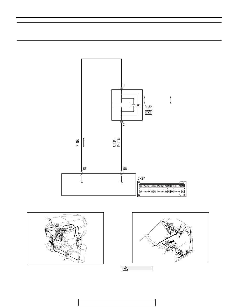
DTC B1B54: Seat Belt Buckle Switch (RH) Circuit (Ground Side) Shorted 


DTC B1B55: Seat Belt Buckle Switch (RH) Circuit (Power Supply Side) Shorted


DTC B1B56: Seat Belt Buckle Switch (RH) Circuit Open 

CAUTION

If DTC B1B54, B1B55 or B1B56 are set in the 
SRS-ECU, always diagnose the CAN main bus 
lines.

.

AC803441

HALL IC

SRS-ECU

PASSENGER'S 
SIDE

SEAT BELT 
SWITCH 

AC

BUCKLE

AC901076

C-27 (Y)

AC

Connector: C-27

AC901079

D-32 (B)

Connector: D-32

AB

SRS AIR BAG DIAGNOSIS

TSB Revision

SUPPLEMENTAL RESTRAINT SYSTEM (SRS)

52B-160

CIRCUIT OPERATION

The SRS-ECU determines whether the seat belt is 
fastened or not according to the connection location 
of the seat belt buckle switch in the seat buckle.

.

DTC SET CONDITIONS

The DTC is set when the seat belt buckle switch out-
put current is not within the specified range.

.

TROUBLESHOOTING HINTS

• Malfunction of the seat belt buckle switch

• Damaged wiring harnesses or connectors 

• Malfunction of the SRS-ECU 

DIAGNOSIS

Required Special Tools:

• MB991222: Probe

• MB991958: Scan Tool (M.U.T.-III Sub Assembly)

• MB991824: Vehicle Communication Interface (V.C.I.)

• MB991827: M.U.T.-III USB Cable

• MB991910: M.U.T.-III Main Harness A (Vehicles with 

CAN communication system)

STEP 1. Using scan tool MB991958, diagnose the CAN bus 
line.

CAUTION

To prevent damage to scan tool MB991958, always turn the 
ignition switch to the "LOCK" (OFF) position before con-
necting or disconnecting scan tool MB991958.
(1) Connect scan tool MB991958. Refer to "How to connect the 

scan tool 

P.52B-28

."

(2) Connect scan tool MB991958 to the data link connector.
(3) Turn the ignition switch to the "ON" position.
(4) Diagnose the CAN bus line.
(5) Turn the ignition switch to the "LOCK" (OFF) position.
Q: Is the CAN bus line found to be normal?

YES : Go to Step 2.
NO :  Repair the CAN bus line (Refer to GROUP 54C, 

Diagnosis 

P.54C-17

).

ZC501967

AC404789

AC701411AB

MB991824

MB991827

MB991910

Data link 
connector

SRS AIR BAG DIAGNOSIS

TSB Revision

SUPPLEMENTAL RESTRAINT SYSTEM (SRS)

52B-161

STEP 2. Recheck for diagnostic trouble code.
Check again if the DTC is set.
(1) Erase the DTC.
(2) Turn the ignition switch to "ON" position.
(3) Check if the DTC is set.
(4) Turn the ignition switch to the "LOCK" (OFF) position.
Q: Is the DTC set?

YES : Go to Step 3
NO :  There is an intermittent malfunction such as poor 

engaged connector(s) or open circuit (Refer to 
GROUP 00, How to Cope with Intermittent 
Malfunction 

P.00-15

).

STEP 3. Check the harness short circuit between seat belt 
buckle switch (passenger’s side) connector D-32 and the 
SRS-ECU connector C-27.
(1) Disconnect the negative battery terminal.
(2) Disconnect passenger’s seat belt buckle switch connector 

D-32.

(3) While pushing the part "A" indicated in the figure of the 

harness side connector, turn the lock lever to the direction 
of the arrow to release the lock lever, and disconnect the 
C-27 SRS-ECU connector.

ZC501967

AC404789

AC701411AB

MB991824

MB991827

MB991910

Data link 
connector

AC507645

A

AC

Lock lever

SRS AIR BAG DIAGNOSIS

TSB Revision

SUPPLEMENTAL RESTRAINT SYSTEM (SRS)

52B-162

(4) Measure the resistance between terminal 55, 58 and body 

ground (DTC B1B54 only).
It should be an open circuit.

(5) Connect the negative battery terminal.
(6) Ignition switch: ON.
(7) Measure the voltage between terminal 55, 58 and body 

ground (No. B1B55 only).
Voltage should measure 1 volt or less.

Q: Is the check result normal?

YES : Go to Step 5
NO :  Go to Step 4.

STEP 4. Check the harness wires between SRS-ECU 
connector C-27 (terminal No.55 and 58) and the 
passenger’s seat belt buckle switch connector D-32 
(terminal No.1 and 2).
Q: Is the check result normal?

YES : Go to Step 6.
NO :  Repair the harness wires between SRS-ECU 

connector C-27 and the passenger’s seat belt buckle 
switch connector D-32. Then go to Step 6.

AC608812

C-27 Harness side 
connector (front view)

CN

AC608813

C-27 Harness side 
connector (front view)

CE


Content   ..  1414  1415  1416  1417   ..