Content .. 1404 1405 1406 1407 ..
Mitsubishi Outlander GS45X. Manual - part 1406
SRS AIR BAG DIAGNOSIS
TSB Revision
SUPPLEMENTAL RESTRAINT SYSTEM (SRS)
52B-119
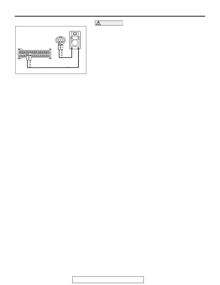
CAUTION
Do not insert a probe into the terminal from D-13 interme-
diate connector front side directly, as the connector con-
tact pressure may be weakened.
(5) Check for continuity between the following terminals. It
should be less than 2 ohms.
• SRS-ECU connector C-27 (terminal No.41) and the
intermediate connector D-13 (terminal No.1)
• SRS-ECU connector C-27 (terminal No.42) and the
intermediate connector D-13 (terminal No.2)
Q: Does continuity exist?
YES : Go to Step 6.
NO : Repair the wiring harness between the C-27 harness
side connector terminal No. 41, 42 and the D-13
intermediate connector (floor harness side) terminal
No. 1, 2.
AC709326
C-27 Harness side
connector (front view)
D-13 Intermediate connector
(Curtain air bag harness side)
(rear view)
AD