Mitsubishi Outlander GS45X. Manual - part 1404


  Index      Mitsubishi     Mitsubishi Outlander GS45X - service repair manual


Search            


Content   ..  1402  1403  1404  1405   ..


Mitsubishi Outlander GS45X. Manual - part 1404


SRS AIR BAG DIAGNOSIS

TSB Revision

SUPPLEMENTAL RESTRAINT SYSTEM (SRS)

52B-111

STEP 2. Recheck for diagnostic trouble code.
Check again if the DTC is set.
(1) Erase the DTC.
(2) Turn the ignition switch to "ON" position.
(3) Check if the DTC is set.
(4) Turn the ignition switch to the "LOCK" (OFF) position.
Q: Is the DTC set?

YES : Go to Step 3.
NO :  There is an intermittent malfunction such as poor 

engaged connector(s) or open circuit (Refer to 
GROUP 00, How to Use Troubleshooting/Inspection 
Service Points 

− How to Cope with Intermittent 

Malfunctions 

P.00-15

).

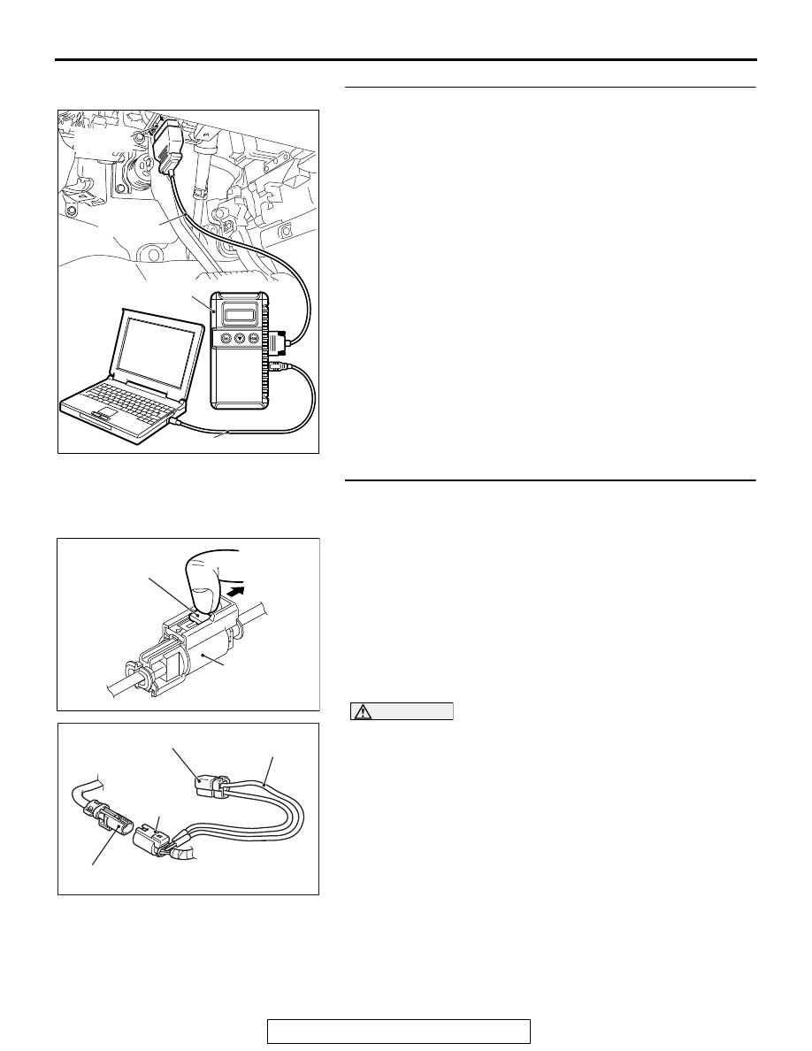
STEP 3. Check by dummy resistor connection. (Using scan 
tool MB991958, read the diagnostic trouble code.)
(1) Disconnect the negative battery terminal.
(2) Disconnect the D-13 intermediate connector, unlock the 

connector by sliding the locking button to the direction of the 
arrow as shown in the figure, and then disconnect the 
connector.

(3) Connect special tool MB991865 to special tool MB991866.

CAUTION

Do not insert a probe into the terminal from its front side 
directly, as the connector contact pressure may be weak-
ened.
(4) Insert the probe of resistor harness, to which the dummy 

resistor is installed, from the back of D-13 intermediate 
connector (floor harness side).

(5) Connect the negative battery terminal.
(6) After erasing the diagnostic trouble code memory, check the 

diagnostic trouble code again.

(7) Disconnect the negative battery terminal.
Q: Is DTC B1B19 set?

YES : Go to Step 4.
NO :  Go to Step 5.

ZC501967

AC404789

AC701411AB

MB991824

MB991827

MB991910

Data link 
connector

AC706606

AH

Locking button

Intermediate 

connector

AC701559

D-13 Intermediate connector
(Curtain air bag harness side)

D-13 
Intermediate
connector
(Floor harness side)


MB991865
(Dummy resistor: 3 

Ω)

MB991866 

(Resistor harness)

AB

SRS AIR BAG DIAGNOSIS

TSB Revision

SUPPLEMENTAL RESTRAINT SYSTEM (SRS)

52B-112

STEP 4. Voltage measurement at the C-27 SRS-ECU 
connector. 
(1) Disconnect the negative battery terminal.
(2) While pushing the part "A" indicated in the figure of the 

harness side connector, turn the lock lever to the direction 
of the arrow to release the lock lever, and disconnect the 
C-27 SRS-ECU connector.

DANGER

To prevent the air bag from deploying unintentionally, 
disconnect the intermediate connector D-13 to short 
the squib circuit.

(3) Disconnect the D-13 intermediate connector, unlock the 

connector by sliding the locking button to the direction of the 
arrow as shown in the figure, and then disconnect the 
connector.

CAUTION

The short spring may not be released due to the insuffi-
cient insertion. Therefore, insert the insulator for 4 mm (0.6 
inch) or more.

(4) Insert a cable tie [3 mm (0.12 inch) wide, 0.5 mm (0.02 inch) 

thick] between terminal 41, 42 and the short spring to 
release the short spring.

(5) Connect the negative battery terminal.
(6) Ignition switch: ON

(7) Measure the voltage between the C-27 wiring harness side 

connector terminal No. 41, 42 and body ground.
Voltage should measure 1 volt or less.

Q: Is the measured voltage within the specified range?

YES : Go to Step 6.
NO :  Repair the wiring harness.

AC506734

A

AB

Lock lever

AC706606

AH

Locking button

Intermediate 

connector

AC507303AI

A

A

C-27 Harness side
connector (front view)

Section
A - A

Cable tie

Short spring

4 mm or more

Terminal

AC709344

C-27 Harness side 
connector (front view)

AC

SRS AIR BAG DIAGNOSIS

TSB Revision

SUPPLEMENTAL RESTRAINT SYSTEM (SRS)

52B-113

STEP 5. Voltage measurement at the D-13 intermediate 
connector.
(1) Disconnect the negative battery terminal.

DANGER

To prevent the air bag from deploying unintentionally, 
disconnect the curtain air bag module connector 
D-109 to short the squib circuit.

(2) Disconnect curtain air bag module (LH) D-109. Use a 

flat-tipped screwdriver to unlock the locking button at the 
harness side connector by withdrawing it toward you in two 
stages, and then disconnect the connector.

(3) Disconnect the D-13 intermediate connector, unlock the 

connector by sliding the locking button to the direction of the 
arrow as shown in the figure, and then disconnect the 
connector.

(4) Because the short spring is installed to the D-13 

intermediate connector (curtain air bag harness side), insert 
a cable tie [3 mm (0.12 inch) wide, 0.5 mm (0.02 inch) thick] 
between terminals 1, 2 and the short spring to release the 
short spring.

(5) Connect the negative battery terminal.
(6) Ignition switch: ON

CAUTION

Do not insert a probe into the terminal from its front side 
directly, as the connector contact pressure may be weak-
ened.
(7) Check for continuity between the D-13 intermediate 

connector (curtain air bag harness side) terminal No. 1, 2 
and the body ground.
Voltage should measure 1 volt or less.

Q: Is the measured voltage within the specified range?

YES : Replace the curtain air bag module (squib) (Refer to 

P.52B-453

). 

NO :  Repair the wiring harness.

AC701573

Locking 
button


Flat-tipped screwdriver

Inflator

Curtain air bag wiring
harness side connector


AB

AC706606

AH

Locking button

Intermediate 

connector

AC700119

D-13 Intermediate 
connector (module side ) 

22 mm or more

Cable tie

Short spring

AK

AC709344

D-13 Intermediate connector 
(Curtain air bag harness side)
(rear view)

AB

SRS AIR BAG DIAGNOSIS

TSB Revision

SUPPLEMENTAL RESTRAINT SYSTEM (SRS)

52B-114

STEP 6. Recheck for diagnostic trouble code. 
Check again if the DTC is set.
(1) Erase the DTC.
(2) Turn the ignition switch to the "ON" position.
(3) Check if the DTC is set.
(4) Turn the ignition switch to the "LOCK" (OFF) position.
Q: Is DTC B1B19 set?

YES : Replace SRS-ECU. (Refer to 

P.52B-436

.)

NO :  Intermittent Malfunction (Refer to GROUP 00, How to 

Use Troubleshooting/Inspection Service Points 

− How 

to Cope with Intermittent Malfunction 

P.00-15

).

ZC501967

AC404789

AC701411AB

MB991824

MB991827

MB991910

Data link 
connector


Content   ..  1402  1403  1404  1405   ..