Mitsubishi Outlander GS45X. Manual - part 1385


  Index      Mitsubishi     Mitsubishi Outlander GS45X - service repair manual


Search            


Content   ..  1383  1384  1385  1386   ..


Mitsubishi Outlander GS45X. Manual - part 1385


SRS AIR BAG DIAGNOSIS

TSB Revision

SUPPLEMENTAL RESTRAINT SYSTEM (SRS)

52B-35

DIAGNOSTIC TROUBLE CODE PROCEDURES <SRS-ECU>

DTC B1206: Passenger’s Air Bag OFF Indicator Light (Open Circuit)

CAUTION

If DTC B1206 is set in the SRS-ECU, always diag-
nose the CAN main bus line.

.

CIRCUIT OPERATION

• Power for the passenger’s air bag OFF indicator 

light is supplied from the fusible link (34).

• The passenger’s air bag OFF indicator light illu-

minates when the ignition switch is turned to the 
"ON" position and goes out after approximately 
seven seconds if there is not a malfunction in the 
SRS system. In the following situations, the indi-
cator will stay on to show that the passenger’s 
(front) air bag is not operational.

CENTER PANEL ASSEMBLY

ETACS-ECU

INTERFACE
CIRCUIT

SRS-ECU

AIR BAG OFF 
INDICATOR 
LIGHT 
PASSENGER'S 
SIDE

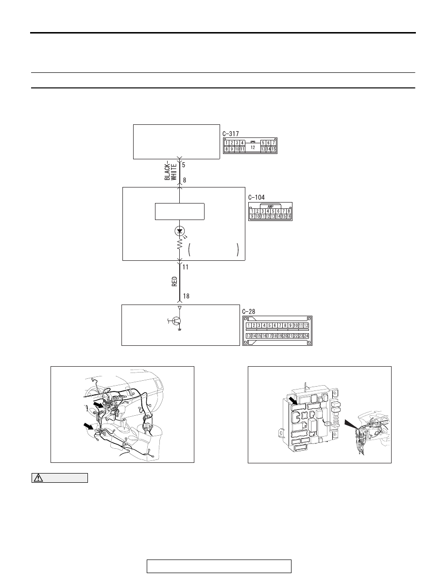
Air Bag OFF Indicator Light Drive Circuit

ACA02789 AB

AC901076

C-28 (Y)

AF

Connectors: C-28, C-104

C-104

ACA02655AF

Connector: C-317

SRS AIR BAG DIAGNOSIS

TSB Revision

SUPPLEMENTAL RESTRAINT SYSTEM (SRS)

52B-36

• The occupant is determined to be less than 

66 lbs (30 kg) by the occupant classifica-
tion-ECU.

• The front passenger’s seat is not occupied.

.

DTC SET CONDITIONS

This DTC will be set if an open circuit has occurred in 
the wiring harness between the passenger’s air bag 
OFF indicator light and the SRS-ECU.

.

TROUBLESHOOTING HINTS

• Damaged wiring harnesses or connectors

• Malfunction of the SRS-ECU

• Malfunction of the passenger’s air bag OFF indi-

cator light

DIAGNOSIS

Required Special Tools:

•  MB991958: Scan Tool (M.U.T.-III Sub Assembly)

• MB991824: Vehicle Communication Interface (V.C.I.)

• MB991827: M.U.T.-III USB Cable

• MB991910: M.U.T.-III Main Harness A (Vehicles with 

CAN Communication System)

STEP 1. Using scan tool MB991958, diagnose the CAN bus 
line.

CAUTION

To prevent damage to scan tool MB991958, always turn the 
ignition switch to the "LOCK" (OFF) position before con-
necting or disconnecting scan tool MB991958.
(1) Connect scan tool MB991958. Refer to "How to connect the 

scan tool 

P.52B-28

."

(2) Turn the ignition switch to the "ON" position.
(3) Diagnose the CAN bus line.
(4) Turn the ignition switch to the "LOCK" (OFF) position.
Q: Is the CAN bus line found to be normal?

YES : Go to Step 2.
NO :  Repair the CAN bus line (Refer to GROUP 54C, 

Diagnosis 

P.54C-17

).

ZC501967

AC404789

AC701411AB

MB991824

MB991827

MB991910

Data link 
connector

SRS AIR BAG DIAGNOSIS

TSB Revision

SUPPLEMENTAL RESTRAINT SYSTEM (SRS)

52B-37

STEP 2. Recheck for diagnostic trouble code.
Check again if the DTC is set.
(1) Erase the DTC.
(2) Turn the ignition switch to the "ON" position.
(3) Check if the DTC is set.
(4) Turn the ignition switch to the "LOCK" (OFF) position.
Q: Is the DTC set?

YES : Go to Step 3.
NO :  There is an intermittent malfunction such as poor 

engaged connector(s) or open circuit (Refer to 
GROUP 00, How to Cope with Intermittent 
Malfunction 

P.00-15

).

STEP 3. Check the passenger’s air bag OFF indicator light.
(1) It is checked whether the passenger’s air bag OFF indicator 

light is normal (Refer to 

P.52B-30

).

Q: Is the check result normal?

YES : Go to Step 4.
NO :  Replace center panel assembly (Refer to GROUP 

52A 

− Instrument Panel Assembly 

P.52A-2

).

ZC501967

AC404789

AC701411AB

MB991824

MB991827

MB991910

Data link 
connector

SRS AIR BAG DIAGNOSIS

TSB Revision

SUPPLEMENTAL RESTRAINT SYSTEM (SRS)

52B-38

STEP 4. Check the harness for open circuit between 
SRS-ECU connector C-28 (terminal No.18) and the center 
panel assembly connector C-104 (terminal No.11).
(1) Disconnect the negative battery terminal.
(2) While pushing the part "A" indicated in the figure of the 

harness side connector, turn the lock lever to the direction 
of the arrow to release the lock lever, and disconnect the 
C-28 SRS-ECU connector.

(3) Disconnect the center panel assembly connector C-104.

(4) Check for continuity between the following terminals. It 

should be less than 2 ohms.

• SRS-ECU connector C-28 (terminal No.18) and the cen-

ter panel assembly connector C-104 (terminal No.11)

Q: Does continuity exist?

YES : Go to Step 5.
NO :  Repair the harness wires.

STEP 5. Measure the voltage at the center panel assembly 
connector.
(1) Disconnect the negative battery terminal.
(2) Disconnect the C-104 center panel assembly connector.
(3) Connect the negative battery terminal.
(4) Ignition switch: ON.
(5) Measure the voltage between the C-104 harness side 

connector terminal No. 8 and body ground.

• The voltage should measure approximately 12 volts 

(battery positive voltage).

Q: Is the measured voltage approximately 12 volts (battery 

positive voltage)?
YES : 
Go to Step 6.
NO :  Repair the wiring harness between the C-317 

ETACS-ECU connector terminal No. 5 and the C-104 
instrument center panel assembly connector terminal 
No. 8.

AC506734

A

AB

Lock lever

AC701497AB

C-28 Harness side 
connector (front view) C-104 Harness 

side connector 
(front view) 

AC608813

C-104 Harness side 
connector (front view)

BS


Content   ..  1383  1384  1385  1386   ..