Mitsubishi Outlander GS45X. Manual - part 1249


  Index      Mitsubishi     Mitsubishi Outlander GS45X - service repair manual


Search            


Content   ..  1247  1248  1249  1250   ..


Mitsubishi Outlander GS45X. Manual - part 1249


PISTON AND CONNECTING ROD

TSB Revision

ENGINE OVERHAUL <2.4L ENGINE>

11B-71

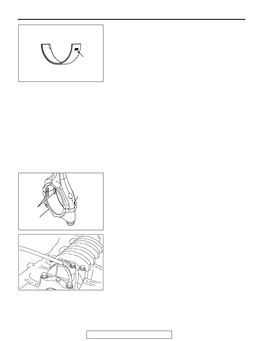
3. A connecting rod bearing has an identification mark at the 

illustrated position.

.

>>F<< CONNECTING ROD CAP INSTALLATION 

NOTE: The connecting rod resulting from the breaking process 
has the high insertion force. The new connecting rod assembly 
may possibly be difficult to remove the connecting rod.
If difficult to remove it, alternately strike the two bolt heads with 
a plastic hammer while the connecting rod bolt is slightly loos-
ened, or strike the center of the cap shaft’s inside diameter 
slightly and outward.
If the outside of the cap is directly struck, the lateral force is 
added to the broken-out section. Thus, pay attention to the bro-
ken-out section that might be difficult to be separated or might 
fall.
Clean the broken-out section before the installation to the 
engine, using compression air.
1. Assemble the bearing cap on the connecting rod by aligning 

it with the mark put during removal. If a new connecting rod 
without a mating mark is used, assemble so that the detent 
notch of the bearing is on the same side as illustrated.

2. Make sure that clearance of the thrust of the connecting rod 

big end is appropriate.

Standard value: 0.10 

 0.25 mm (0.004  0.010 inch)

Limit: 0.4 mm (0.016 inch)

.

AK700793AD

Identification
mark

AK503157

2

Cylinder No.

AE

Notch

Front mark

AK502752

PISTON AND CONNECTING ROD

TSB Revision

ENGINE OVERHAUL <2.4L ENGINE>

11B-72

>>G<< CONNECTING ROD CAP BOLT 
INSTALLATION

1. Check in the following procedure before reusing the 

connecting rod bolt.

(1) Measure the outside diameter "A."
(2) Measure the smallest outside diameter "B" within the 

range "X" shown in the illustration.

(3) If the difference of outside diameter of thread exceeds 

the limit, replace the connecting rod bolt.

Limit: 0.1 mm (0.004 inch)

2. Apply engine oil to the threaded portion and seat surface of 

the bolt before installing it.

3. After installing each bolt and tightening it by fingers, tighten 

bolts alternately to properly assemble the cap.

4. Tighten the bolt in several steps until the torque reaches 5.0 

N

⋅m (44 in-lb).

5. Tighten the bolt in several steps until the torque reaches 20 

N

⋅m (14 ft-lb).

6. Put a paint mark on the bolt head as illustrated.
7. Put a paint mark on the connecting rod at 90

° position in the 

tightening direction of the bolt with reference to the paint 
mark position of the bolt.

CAUTION

• When the tightening angle is smaller than the specified 

tightening angle, the appropriate tightening capacity 
cannot be secured.

• When the tightening angle is larger than the specified 

tightening angle, remove the bolt to start from the 
beginning again according to the procedure.

8. Tighten the bolt 90

°, and make sure that the paint mark of 

the connecting rod is aligned with that of the bolt.

INSPECTION

M1113008502123

.

PISTON RINGS

1. Check clearance between piston rings and ring grooves. If 

the limit is exceeded, replace piston rings or piston, or both.

Standard value:

Number 1 ring: 0.03 

 0.07 mm (0.001  0.003 inch)

Number 2 ring: 0.03 

 0.07 mm (0.001  0.003 inch) 

Limit: 0.1 mm (0.004 inch)

AK604589AD

20.5 mm (0.81 in)

35 mm (1.38 in)

A

B

B

X

AK502749

90˚

Paint mark

AD

Paint mark

AK502751

PISTON AND CONNECTING ROD

TSB Revision

ENGINE OVERHAUL <2.4L ENGINE>

11B-73

2. Put piston rings into the cylinder bore, press them against 

the piston top face, and push them in. After achieving 
squareness, measure the end gap with a free gauge. If the 
end gap is excessive, replace piston rings.

Standard value:

Number 1 ring: 0.15 

 0.25 mm (0.006  0.011 inch)

Number 2 ring: 0.25 

 0.40 mm (0.010  0.016 inch)

Oil ring: 0.10 

 0.35 mm (0.004  0.014 inch)

Limit:

Number 1 ring: 0.8 mm (0.03 inch)
Number 2 ring: 0.8 mm (0.03 inch)
Oil ring: 1.0 mm (0.04 inch)

.

CRANKSHAFT PIN OIL CLEARANCE 
(PLASTIGAGE METHOD)

1. Wipe oil off the crankshaft pin and connecting rod bearing.
2. Place a plastigage in length equal to the bearing width on 

the pin shaft straight in alignment with the shaft center.

3. Carefully install the connecting rod cap and tighten bolts to 

the specified tightening torque of 5.0 N

⋅m (44 in-lb) → 20 

N

⋅m (15 ft-lb) → +90°.

4. Remove bolts and gently remove the connecting rod cap.

5. Measure the crushed plastigage width (area most widely 

crushed) using a scale printed on the plastigage bag.

Standard value: 0.018 

 0.045 mm (0.0007  0.0018 

inch)
Limit: 0.1 mm (0.04 inch)

AK503370AF

Please down ring 
with piston

End gap

Piston ring

Front mark

AK503373 AD

Plastigage

AK503374AD

Plastigage

CRANKSHAFT AND CYLINDER BLOCK

TSB Revision

ENGINE OVERHAUL <2.4L ENGINE>

11B-74

CRANKSHAFT AND CYLINDER BLOCK

REMOVAL AND INSTALLATION

M1113008703238

AK502938AE

5

26.5 ± 2.0 N·m 

 +45˚

20 ± 1 ft-lb

6

7

11 ± 1 N·m
98 ± 8 in-lb

8

4

3

2

1

Apply engine oil to
all moving parts
before installation.

Removal steps 

>>E<<

1. Crankshaft bearing cap bolt

>>E<<

2. Crankshaft bearing cap

>>D<<

3. Crankshaft bearing lower

<<A>>

4. Crankshaft

>>C<<

5. Crankshaft bearing upper

>>B<<

6. Thrust bearing

>>A<<

7. Crankshaft sensing ring
8. Cylinder block

Removal steps (Continued)


Content   ..  1247  1248  1249  1250   ..