Mitsubishi Outlander GS45X. Manual - part 1218


  Index      Mitsubishi     Mitsubishi Outlander GS45X - service repair manual


Search            


Content   ..  1216  1217  1218  1219   ..


Mitsubishi Outlander GS45X. Manual - part 1218


TIMING BELT

TSB Revision

ENGINE OVERHAUL <3.0L ENGINE>

11D-25

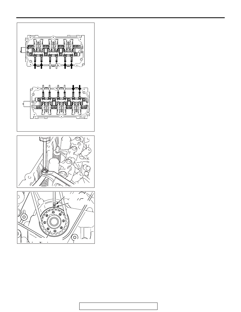
4. Measure the valve clearances marked with arrows shown in 

the illustration.
A: When Number1 cylinder is on the top dead center of 
compression stroke.
B: When Number4 cylinder is on the top dead center of 
compression stroke.
NOTE: The valve clearance adjustment at the exhaust side 
is not necessary because the auto lash adjuster exists.

5. Using a thickness gauge, adjust the clearance between the 

valve stem end and the adjusting screw.

Standard value: 0.07 

 0.13 mm (0.003  0.005 inch)

6. Hold the adjusting screw not rotating through a driver and 

then tighten the rock nut.

7. Rotate the crankshaft one time clockwise and then align the 

timing mark with the timing mark on the crankshaft sprocket. 
(Place Number 4 cylinder on the top dead center of 
compression stroke.)

8. Adjust the valve clearance for the rest of the valves.
9. Install the rocker cover and ignition coil.

AK600846

A

A

B

B

B

B

Right bank

Left bank

A

A

A

B

B

A

AC

<Intake side>

<Exhaust side>

<Exhaust side>

1

3

5

2

4

6

AK600896

AK600822 AC

Timing mark

Timing mark

Crankshaft sprocket

INTAKE MANIFOLD

TSB Revision

ENGINE OVERHAUL <3.0L ENGINE>

11D-26

INTAKE MANIFOLD

REMOVAL AND INSTALLATION

M1113002700684

Required Special Tools:

• MB991398: Spark Plug Wrench

• MB992106: O-ring Installer

AKA00760

8

1

2

3

5

4

7

9

10

11

11

6

12 ± 1 N·m
104 ± 9 in-lb

9.5 ± 2.5 N·m
84 ± 22 in-lb

18 ± 2 N·m
13 ± 1 ft-lb

22 ± 1 N·m
16 ± 1 ft-lb

AB

Removal steps 

1.

Ignition coil

<<A>> >>E<<

2.

Spark plugs

3.

Fuel rail and injector

4.

Insulator

>>D<<

5.

Injector support

>>C<<

6.

O-ring

>>B<<

7.

Injector

8.

O-ring

9.

Fuel rail

>>A<<

10. Intake manifold
11. Intake manifold gasket

Removal steps (Continued)

INTAKE MANIFOLD

TSB Revision

ENGINE OVERHAUL <3.0L ENGINE>

11D-27

REMOVAL SERVICE POINT

.

<<A>> SPARK PLUG REMOVAL

Using special tool MB991398, removal the spark plug.

INSTALLATION SERVICE POINTS

.

>>A<< INTAKE MANIFOLD INSTALLATION

1. Tighten the nuts on the left bank to 6.5 

± 1.5 N⋅m (58 ± 13 

in-lb).

2. Tighten the nuts on the right bank to the specified torque.

Tightening torque: 22 

± 1 Nm (16 ± 1 ft-lb)

3. Tighten the nuts on the left bank to the specified torque.

Tightening torque: 22 

± 1 Nm (16 ± 1 ft-lb)

4. Tighten the nuts on the right bank and those on the left bank 

again in that order.

Tightening torque: 22 

± 1 Nm (16 ± 1 ft-lb)

.

>>B<< INJECTOR INSTALLATION

1. Apply clean gasoline to the O-ring.
2. Insert the injector into the fuel rail.
3. Make sure the injector rotates smoothly. If not, remove the 

injector to check the O-ring for damage, and replace the 
O-ring if necessary. Then reinsert the injector and check that 
it rotates smoothly.

.

AK600875

MB991398

AD

Spark plug

AK600876

Timing belt side

Right bank

Left bank

AC

AK600877

Delivery pipe

Injector

AC

INTAKE MANIFOLD

TSB Revision

ENGINE OVERHAUL <3.0L ENGINE>

11D-28

>>C<< O-RING INSTALLATION 

When inserting an O-ring into the injector on the injection noz-
zle side, use special tool MB992106 to gradually expand the 
O-ring, and fit it in place.

.

>>D<< INJECTOR SUPPORT INSTALLATION 

1. Make sure that the protrusion of the injector is at the center 

as shown in the illustration.

2. Securely assemble the injector to the injector groove and 

fuel rail collar.

.

>>E<< SPARK PLUG INSTALLATION 

Using special tool MB991398, tighten the spark plug to the 
specified torque.

Tightening torque: 18 

± 2 Nm (13 ± 1 ft-lb)

AK600790

MB992106

O-ring

AC

AK600878

AK800066

AK600875

MB991398

AD

Spark plug


Content   ..  1216  1217  1218  1219   ..