Mitsubishi Outlander GS45X. Manual - part 1100


  Index      Mitsubishi     Mitsubishi Outlander GS45X - service repair manual


Search            


Content   ..  1098  1099  1100  1101   ..


Mitsubishi Outlander GS45X. Manual - part 1100


SUNROOF

TSB Revision

BODY

42A-203

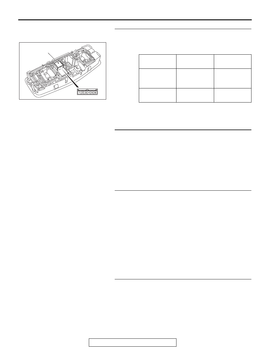
STEP 3. Sunroof switch check
(1) Remove the sunroof switch. Refer to 

P.42A-217

.

(2) Check continuity when the sunroof switch is operated to 

"CLOSE/TILT-DOWN" position.

Q: Is the sunroof switch normal?

YES : Go to Step 4.
NO :  Replace the sunroof switch.

STEP 4. Check sunroof motor assembly connector D-04 
for loose, corroded or damaged terminals, or terminals 
pushed back in the connector.
Q: Is sunroof motor assembly connector D-04 in good 

condition?
YES : 
Go to Step 5.
NO :  Repair or replace the damaged component(s). Refer 

to GROUP 00E, Harness Connector Inspection 

P.00E-2

. Check that the sunroof works normally.

STEP 5. Check the wiring harness between sunroof switch 
connector D-03 (terminal 6) and sunroof motor assembly 
connector D-04 (terminal 10). 

• Check the power supply line for open circuit and short cir-

cuit.

Q: Is the wiring harness between sunroof switch connector 

D-03 (terminal 6) and sunroof motor assembly 
connector D-04 (terminal No. 10) in good condition?
YES : 
Go to Step 6.
NO :  The wiring harness may be damaged or the 

connector(s) may have loose, corroded or damaged 
terminals, or terminals pushed back in the connector. 
Repair the wiring harness as necessary. Check that 
the sunroof works normally.

STEP 6. Retest the system.
Check that the sunroof lid glass tilts down or closes normally.
Q: Is the check result normal?

YES : No action is necessary and testing is complete.
NO :  Replace the sunroof motor assembly. Check that the 

sunroof works normally.

Switch 
position

Terminal No.

Normal value

Close/tilt-down

− 6

Continuity 
exists (2 

Ω or 

less)

OFF

− 4, 4 − 5, 4 − 

6

Open circuit

AC703554AB

Sunroof switch 

SUNROOF

TSB Revision

BODY

42A-204

INSPECTION PROCEDURE 5: Sunroof Safety Function does not Work Normally.

CAUTION

Before replacing the ECU, ensure that the power supply circuit, the ground circuit and the communi-
cation circuit are normal.

.

CIRCUIT OPERATION

Malfunction of the sunroof motor assembly or incor-
rect learning of the sunroof fully closed position is 
suspected.

.

TROUBLESHOOTING HINTS

• Malfunction of the sunroof motor assembly

• Incorrect learning of the sunroof fully closed posi-

tion

DIAGNOSTIC PROCEDURE

Required Special Tools:

• MB992006: Extra fine probe

• MB991223: Harness set

• MB991958: Scan Tool (M.U.T.-III Sub Assembly)

• MB991824: Vehicles Communication Interface (V.C.I.)

• MB991827: M.U.T.-III USB Cable

• MB991910: M.U.T.-III Main Harness A (Vehicles with 

CAN communication system)

STEP 1. Using scan tool MB991958, read the diagnostic 
trouble code.

CAUTION

To prevent damage to scan tool MB991958, always turn the 
ignition switch to the "LOCK" (OFF) position before con-
necting or disconnecting scan tool MB991958.
(1) Connect scan tool MB991958. Refer to GROUP 42B, "How 

to connect scan tool (M.U.T.-III) 

P.42B-13

."

(2) Turn the ignition switch to the "ON" position.
(3) Check whether the ETACS-ECU related DTC is set.
(4) Turn the ignition switch to the "LOCK" (OFF) position.
Q: Is the DTC set?

YES : Diagnose the sunroof motor assembly. Refer to 

Diagnostic trouble code chart 

P.42A-180

.

NO :  Go to Step 2.

ZC501967

AC404789

AC701411AB

MB991824

MB991827

MB991910

Data link 
connector

SUNROOF

TSB Revision

BODY

42A-205

STEP 2. Check the trouble symptom.
Check the sunroof trouble symptom according to the following 
procedures.
(1) Carry out the learning procedures of the sunroof fully closed 

position (Refer to 

P.42A-212

).

(2) Check the trouble symptom.
Q: Is the check result normal?

YES : No action is necessary and testing is complete.
NO :  Replace the sunroof motor assembly. Check that the 

sunroof works normally.

INSPECTION PROCEDURE 6: Sunroof Timer Lock Function does not Work Normally.

CAUTION

Before replacing the ECU, ensure that the power 
supply circuit, the ground circuit and the com-
munication circuit are normal.

.

CIRCUIT OPERATION

• The sunroof timer function works according to the 

signals from the following switches:

• Ignition switch (IG1): OFF

• Front door switch (LH): OFF

• Front door switch (RH): OFF

• Vehicle condition

• Ignition switch: LOCK (OFF) position

• Front door (LH): Closed

• Front door (RH): Closed

• When the driver’s door or the passenger’s door 

are opened and closed while the sunroof timer 
function is on, the sunroof operative duration will 
be changed.

.

TECHNICAL DESCRIPTION (COMMENT)

If the sunroof timer function does not work normally, 
the input circuits from the switches described in 
"CIRCUIT OPERATION", the sunroof motor assem-
bly, the ETACS-ECU or the LIN communication line 
may be defective.

.

TROUBLESHOOTING HINTS

• The front door switch may be defective

• The sunroof motor assembly may be defective

• The wiring harness or connectors may have 

loose, corroded, or damaged terminals, or termi-
nals pushed back in the connector

.

PROBABLE CAUSES

• Malfunction of the driver's door switch

• Malfunction of the sunroof motor assembly

• Malfunction of ETACS-ECU

• Damaged wiring harness and connectors

DIAGNOSTIC PROCEDURE

Required Special Tools:

• MB992006: Extra fine probe

• MB991223: Harness set

• MB991958: Scan Tool (M.U.T.-III Sub Assembly)

• MB991824: Vehicles Communication Interface (V.C.I.)

• MB991827: M.U.T.-III USB Cable

• MB991910: M.U.T.-III Main Harness A (Vehicles with 

CAN communication system)

SUNROOF

TSB Revision

BODY

42A-206

STEP 1. Check the power supply system.
With the ignition switch in the LOCK (OFF) position, check if 
the following function operates normally:

• Hazard warning light

• Central door locking system

Q: Is the check result normal?

YES : Go to Step 2.
NO :  Refer to GROUP 54A, Malfunction of ETACS-ECU 

power supply circuit 

P.54A-825

?.

STEP 2. Using scan tool MB991958, read the diagnostic 
trouble code.

CAUTION

To prevent damage to scan tool MB991958, always turn the 
ignition switch to the "LOCK" (OFF) position before con-
necting or disconnecting scan tool MB991958.
(1) Connect scan tool MB991958. Refer to GROUP 42B, "How 

to connect scan tool (M.U.T.-III) 

P.42B-13

."

(2) Turn the ignition switch to the "ON" position.
(3) Check whether the ETACS-ECU related DTC is set.
(4) Turn the ignition switch to the "LOCK" (OFF) position.
Q: Is the DTC set?

YES : Diagnose the ETACS-ECU. Refer to GROUP 54A, 

Diagnosis 

P.54A-825

?.

NO :  Go to Step 3.

ZC501967

AC404789

AC701411AB

MB991824

MB991827

MB991910

Data link 
connector


Content   ..  1098  1099  1100  1101   ..