Content .. 1097 1098 1099 1100 ..
Mitsubishi Outlander GS45X. Manual - part 1099
SUNROOF
TSB Revision
BODY
42A-199
DIAGNOSTIC PROCEDURE
Required Special Tools:
• MB992006: Extra fine probe
• MB991223: Harness set
• MB991958: Scan Tool (M.U.T.-III Sub Assembly)
• MB991824: Vehicles Communication Interface (V.C.I.)
• MB991827: M.U.T.-III USB Cable
• MB991910: M.U.T.-III Main Harness A (Vehicles with
CAN communication system)
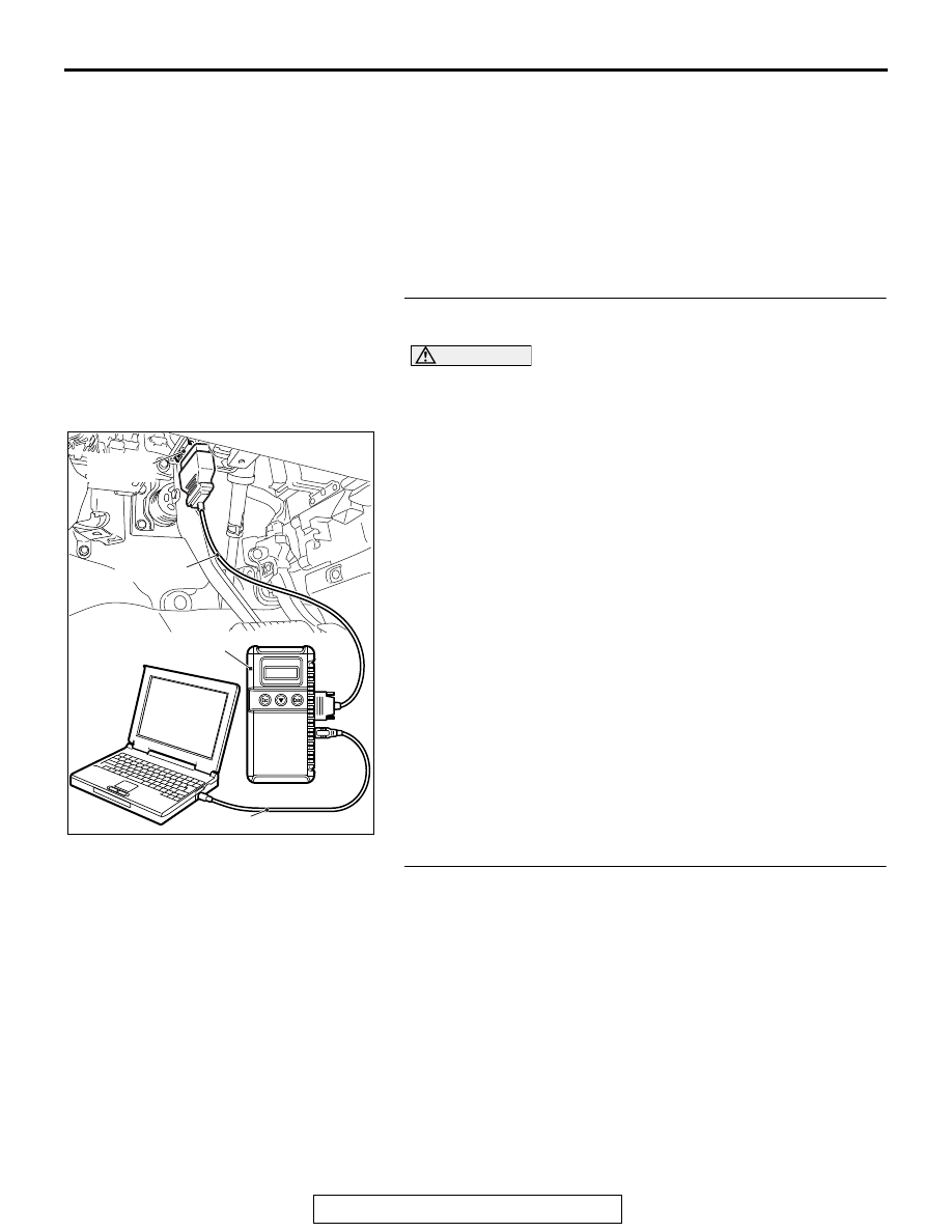
STEP 1. Using scan tool MB991958, read the diagnostic
trouble code.
CAUTION
To prevent damage to scan tool MB991958, always turn the
ignition switch to the "LOCK" (OFF) position before con-
necting or disconnecting scan tool MB991958.
(1) Connect scan tool MB991958. Refer to GROUP 42B, "How
to connect scan tool (M.U.T.-III)
P.42B-13
."
(2) Turn the ignition switch to the "ON" position.
(3) Check whether the ETACS-ECU related DTC is set.
(4) Turn the ignition switch to the "LOCK" (OFF) position.
Q: Is the DTC set?
YES : Diagnose the ETACS-ECU. Refer to
.
NO : Go to Step 2.
STEP 2. Check sunroof switch connector D-03 for loose,
corroded or damaged terminals, or terminals pushed back
in the connector.
Q: Is sunroof switch connector D-03 in good condition?
YES : Go to Step 3.
NO : Repair or replace the damaged component(s). Refer
to GROUP 00E, Harness Connector Inspection
. Check that the sunroof works normally.
ZC501967
AC404789
AC701411AB
MB991824
MB991827
MB991910
Data link
connector