Mitsubishi Outlander GS45X. Manual - part 1078


  Index      Mitsubishi     Mitsubishi Outlander GS45X - service repair manual


Search            


Content   ..  1076  1077  1078  1079   ..


Mitsubishi Outlander GS45X. Manual - part 1078


DOOR

TSB Revision

BODY

42A-115

STEP 26. Check ETACS-ECU connector C-311 for loose, 
corroded or damaged terminals, or terminals pushed back 
in the connector.
Q: Is ETACS-ECU connector C-311 in good condition?

YES : Go to Step 27.
NO :  Repair or replace the damaged component(s). Refer 

to GROUP 00E, Harness Connector Inspection 

P.00E-2

. When the rear power window sub switch 

(RH) is operated, the rear power window (RH) should 
raise and lower normally.

STEP 27. Check the wiring harness between ETACS-ECU 
connector C-311 (terminal 12) and rear power window sub 
switch (RH) connector E-11 (terminal 6).

• Check the power supply line for open circuit and short cir-

cuit.

NOTE: Also check intermediate connectors D-36. If intermedi-
ate connector D-36 is damaged, repair or replace the connector 
as described in GROUP 00E, Harness Connector Inspection 

P.00E-2

.

Q: Is the wiring harness between ETACS-ECU connector 

C-311 (terminal 12) and rear power window sub switch 
(RH) connector E-11 (terminal 6) in good condition?
YES : 
No action is necessary and testing is complete.
NO :  The wiring harness may be damaged or the 

connector(s) may have loose, corroded or damaged 
terminals, or terminals pushed back in the connector. 
Repair the wiring harness as necessary. When the 
rear power window sub switch (RH) is operated, the 
rear power window (RH) should raise and lower 
normally.

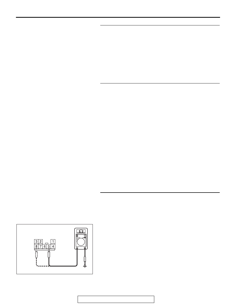
STEP 28. Check the ground circuit to the rear power 
window sub switch (RH). Measure the resistance at rear 
power window sub switch (RH) connector E-11.
(1) Disconnect rear power window sub switch (RH) connector 

E-11 and measure the resistance available at the wiring 
harness side of the connector.

(2) Measure the resistance value between terminal 5 and 

ground, and also between terminal 8 and ground.

• The resistance should be 2 ohms or less.

Q: Is the measured resistance 2 ohms or less?

YES : Go to Step 30.
NO :  Go to Step 29.

AC702473AJ

Connector E-11
(harness side)

DOOR

TSB Revision

BODY

42A-116

STEP 29. Check the wiring harness between power 
window main switch connector E-19 (terminals 15, 17) and 
rear power window sub switch (RH) connector E-11 
(terminals 5, 8).

• Check the power supply lines for open circuit and short cir-

cuit.

NOTE: Also check intermediate connectors C-20, C-126 and 
D-36. If intermediate connector C-20, C-126 or D-36 is dam-
aged, repair or replace the damaged component(s) as 
described in GROUP 00E, Harness Connector Inspection 

P.00E-2

.

Q: Is the wiring harness between power window main 

switch connector E-19 (terminals 15, 17) and rear power 
window sub switch (RH) connector E-11 (terminals 5, 8) 
in good condition?
YES : 
Replace the power window main switch. When the 

rear power window sub switch (RH) is operated, the 
rear power window (RH) should raise and lower 
normally.

NO :  The wiring harness may be damaged or the 

connector(s) may have loose, corroded or damaged 
terminals, or terminals pushed back in the connector. 
Repair the wiring harness as necessary. When the 
rear power window sub switch (RH) is operated, the 
rear power window (RH) should raise and lower 
normally.

STEP 30. Check the wiring harness between rear power 
window sub switch (RH) connector E-11 (terminals 4, 7) 
and rear power window motor (RH) connector E-12 
(terminals 4, 1).

• Check the power supply lines for open circuit and short cir-

cuit.

Q: Is the wiring harness between rear power window sub 

switch (RH) connector E-11 (terminals 4, 7) and rear 
power window motor (RH) connector E-12 (terminals 4, 
1) in good condition?
YES : 
No action is necessary and testing is complete.
NO :  The wiring harness may be damaged or the 

connector(s) may have loose, corroded or damaged 
terminals, or terminals pushed back in the connector. 
Repair the wiring harness as necessary. When the 
rear power window sub switch (RH) is operated, the 
rear power window (RH) should raise and lower 
normally.

DOOR

TSB Revision

BODY

42A-117

INSPECTION PROCEDURE C-4: Front and/or Rear Passenger's Power Window(s) do not work by 
means of the Power Window Main Switch.

CAUTION

Before replacing the ECU, ensure that the power 
supply circuit, the ground circuit and the com-
munication circuit are normal.

ACA01306AC

Power window (Front Passenger's side) Circuit

BLA

CK

BLA

CK

BLA

CK

BLA

CK

RED

RED

GREEN

GREEN

BLUE-

WHITE

BLUE-

WHITE

WHITE-

BLA

CK

GREEN

FRONT 
(RH)

LOCK
SWITCH

POWER 
WINDOW 
MAIN SWITCH

VIOLET

BLUE

FRONT
POWER
WINDOW
SUB
SWITCH

FRONT
POWER
WINDOW
MOTOR (RH)

ETACS-ECU

POWER 
WINDOW 
RELAY

E-19

C-126

C-112

E-06

E-03

DOOR

TSB Revision

BODY

42A-118

ACA01307

BLA

CK

REAR 
(LH)

REAR 
(RH)

LOCK
SWITCH

POWER WINDOW MAIN SWITCH

BLA

CK

BLA

CK

BLA

CK

RED

RED

BR

O

W

N

BR

O

W

N

BR

O

W

N

BR

O

W

N

YELLO

W

YELLO

W

YELLO

W

YELLO

W

GRA

Y

YELLO

W

GRA

Y

GRA

Y

GRA

Y

BLUE

BLUE

BLUE

BLUE

WHITE

WHITE

WHITE

WHITE

REAR
POWER
WINDOW
SUB SWITCH 
(LH)

REAR
POWER
WINDOW
MOTOR (LH)

REAR
POWER
WINDOW
SUB SWITCH 
(RH)

REAR
POWER
WINDOW
MOTOR (RH)

AC

Power window (Rear Door) Circuit

BLUE-WHITE

ETACS-ECU

POWER 
WINDOW 
RELAY

E-19

C-20

D-36

C-32

D-21

C-126

E-11

E-12


Content   ..  1076  1077  1078  1079   ..