Mitsubishi Outlander GS45X. Manual - part 1076


  Index      Mitsubishi     Mitsubishi Outlander GS45X - service repair manual


Search            


Content   ..  1074  1075  1076  1077   ..


Mitsubishi Outlander GS45X. Manual - part 1076


DOOR

TSB Revision

BODY

42A-107

STEP 8. Check ETACS-ECU connector C-315 for loose, 
corroded or damaged terminals, or terminals pushed back 
in the connector.
Q: Is ETACS-ECU connector C-315 in good condition?

YES : Go to Step 9.
NO :  Repair or replace the damaged component(s). Refer 

to GROUP 00E, Harness Connector Inspection 

P.00E-2

. When the front power window sub switch 

(RH) is operated, the front power window (RH) should 
raise and lower normally.

STEP 9. Check the wiring harness between ETACS-ECU 
connector C-315 (terminal 8) and front power window sub 
switch connector E-06 (terminal 6).

• Check the power supply line for open circuit and short cir-

cuit.

NOTE: Also check intermediate connector C-112. If intermedi-
ate connectors C-112 is damaged, repair or replace the dam-
aged component(s) as described in GROUP 00E, Harness 
Connector Inspection 

P.00E-2

.

Q: Is the wiring harness between ETACS-ECU connector 

C-315 (terminal 8) and front power window sub switch 
connector E-06 (terminal 6 in good condition?
YES : 
No action is necessary and testing is complete.
NO :  The wiring harness may be damaged or the 

connector(s) may have loose, corroded or damaged 
terminals, or terminals pushed back in the connector. 
Repair the wiring harness as necessary. When the 
front power window sub switch is operated, the front 
power window (RH) should raise and lower normally.

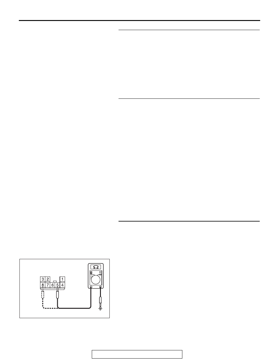
STEP 10. Check the ground circuit to the front power 
window sub switch. Measure the resistance at front power 
window sub switch connector E-06.
(1) Disconnect front power window sub switch connector E-06 

and measure the resistance available at the wiring harness 
side of the connector.

(2) Measure the resistance value between terminal 5 and 

ground, and also between terminal 8 and ground.

• The resistance should be 2 ohms or less.

Q: Is the measured resistance 2 ohms or less?

YES : Go to Step 12.
NO :  Go to Step 11.

AC702473

Connector E-06

AI

(harness side)

DOOR

TSB Revision

BODY

42A-108

STEP 11. Check the wiring harness between power window 
main switch connector E-19 (terminals 1, 3) and front 
power window sub switch connector E-06 (terminals 8, 5).

• Check the power supply lines for open circuit and short cir-

cuit.

NOTE: Also check intermediate connectors C-112 and C-126. 
If intermediate connector C-112 or C-126 is damaged, repair or 
replace the damaged component(s) as described in GROUP 
00E, Harness Connector Inspection 

P.00E-2

.

Q: Is the wiring harness between power window main 

switch connector E-19 (terminals 1, 3) and front power 
window sub switch connector E-06 (terminals 8, 5) in 
good condition?
YES : 
Replace the power window main switch. When the 

front power window sub switch (RH) is operated, the 
front power window (RH) should raise and lower 
normally.

NO :  The wiring harness may be damaged or the 

connector(s) may have loose, corroded or damaged 
terminals, or terminals pushed back in the connector. 
Repair the wiring harness as necessary. When the 
front power window sub switch (RH) is operated, the 
front power window (RH) should raise and lower 
normally.

STEP 12. Check the wiring harness between front power 
window sub switch connector E-06 (terminals 4, 7) and 
front power window motor (RH) connector E-03 (terminals 
1, 4).

• Check the power supply lines for open circuit and short cir-

cuit.

Q: Is the wiring harness between front power window sub 

switch connector E-06 (terminals 4, 7) and front power 
window motor (RH) connector E-03 (terminals 1, 4) in 
good condition?
YES : 
No action is necessary and testing is complete.
NO :  The wiring harness may be damaged or the 

connector(s) may have loose, corroded or damaged 
terminals, or terminals pushed back in the connector. 
Repair the wiring harness as necessary. When the 
front power window sub switch (RH) is operated, the 
front power window (RH) should raise and lower 
normally.

DOOR

TSB Revision

BODY

42A-109

STEP 13. Check rear power window sub switch (LH) 
connector E-25 and rear power window motor (LH) 
connector E-26 for loose, corroded or damaged terminals, 
or terminals pushed back in the connector.
Q: Are rear power window sub switch (LH) connector E-25 

and rear power window motor (LH) connector E-26 in 
good condition?
YES : 
Go to Step 14.
NO :  Repair or replace the damaged component(s). Refer 

to GROUP 00E, Harness Connector Inspection 

P.00E-2

. When the rear power window sub switch 

(LH) is operated, the rear power window (LH) should 
raise and lower normally.

STEP 14. Check the rear power window sub switch (LH) for 
continuity.
(1) Remove the rear power window sub switch (LH). Refer to 

GROUP 42A, Door, Door Glass and Regulato

P.42A-148

.

(2) Check continuity when the rear power window sub switch 

(LH) is operated to "UP" or "DOWN" position.

Q: Is the rear power window sub switch (LH) normal?

YES : Go to Step 15.
NO :  Replace the rear power window sub switch (LH). 

When the rear power window sub switch (LH) is 
operated, the rear power window (LH) should raise 
and lower normally.

Switch 
position

Tester 
connection

Specified 
condition

UP

− 5, 6 − 7

Continuity 
exists (2 

Ω or 

less)

OFF

− 5, 7 − 8

DOWN

− 6, 7 − 8

AC703138AB

8

3

4 5

1

2

6 7

<Rear door>

DOOR

TSB Revision

BODY

42A-110

STEP 15. Check the rear power window motor (LH).
(1) Remove the rear power window regulator assembly (LH). 

Refer to GROUP 42A, Door, Door Glass and Regulator 

P.42A-148

.

(2) Connect a battery to the motor terminal, and check that the 

motor runs freely.

Q: Is the rear power window motor (LH) normal?

YES : Go to Step 16.
NO :  Replace the rear power window motor (LH). When the 

rear power window sub switch (LH) is operated, the 
rear power window (LH) should raise and lower 
normally.

STEP 16. Check the battery power supply circuit to the rear 
power window sub switch (LH). Measure the voltage at rear 
power window sub switch (LH) connector E-25.
(1) Disconnect rear power window sub switch (LH) connector 

E-25 and measure the voltage available at the wiring 
harness side of the connector.

(2) Measure the voltage between terminal 6 and ground.

• The voltage should measure approximately 12 volts 

(battery positive voltage).

Q: Is the measured voltage approximately 12 volts (battery 

positive voltage)?
YES : 
Go to Step 19.
NO :  Go to Step 17.

Battery connection

Slider position

• Connect terminal 1 to 

the negative battery 
terminal

• Connect terminal 4 to 

the positive battery 
terminal

UP

• Connect terminal 4 to 

the negative battery 
terminal

• Connect terminal 1 to 

the positive battery 
terminal

DOWN

AC703136AB

AC702474

Connector E-25

AI

(harness side)


Content   ..  1074  1075  1076  1077   ..