Mitsubishi Outlander GS45X. Manual - part 1061


  Index      Mitsubishi     Mitsubishi Outlander GS45X - service repair manual


Search            


Content   ..  1059  1060  1061  1062   ..


Mitsubishi Outlander GS45X. Manual - part 1061


DOOR

TSB Revision

BODY

42A-47

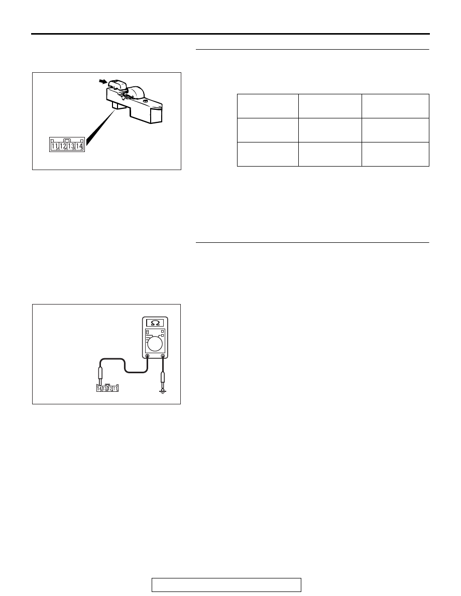
STEP 3. Check the front power window sub switch (door 
lock switch).
Remove the front power window sub switch. Refer to 

P.42A-148

.

Q: Does the front power window sub switch work 

normally?
YES : 
Go to Step 4.
NO :  Replace the front power window sub switch. Verify 

that all the doors can be locked and unlocked 
normally.

STEP 4. Check the ground circuit to the front power 
window sub switch. Measure the resistance at front power 
window sub switch connector E-05.
(1) Disconnect front power window sub switch connector E-05 

and measure the resistance available at the wiring harness 
side of the connector.

(2) Measure the resistance value between terminal 14 and 

ground.

• The resistance should be 2 ohms or less.

Q: Is the measured resistance 2 ohms or less?

YES : Go to Step 6.
NO :  Go to Step 5.

Switch 
position

Tester 
connection

Specified 
condition

LOCK

13 

− 14

Continuity exists 
(2 

Ω or less)

UNLOCK

12 

− 14

Continuity exists 
(2 

Ω or less)

AC703356

Door lock switch

AC

AC209731

Connector E-05
(Harness side)

AC208731CE

DOOR

TSB Revision

BODY

42A-48

STEP 5. Check the wiring harness between front power 
window sub switch connector E-05 (terminal No. 14) and 
ground. 

• Check the ground line for open circuit.

NOTE: Also check intermediate connector C-112 for loose, cor-
roded, or damaged terminals, or terminals pushed back in the 
connector. If intermediate connector C-112 is damaged, repair 
or replace the damaged component(s) as described in GROUP 
00E, Harness Connector Inspection 

P.00E-2

.

Q: Is the wiring harness between front power window sub 

switch connector E-05 (terminal No. 14) and ground in 
good condition?
YES : 
Go to Step 6.
NO :  The wiring harness may be damaged or the 

connector(s) may have loose, corroded or damaged 
terminals, or terminals pushed back in the connector. 
Repair the wiring harness as necessary.

STEP 6. Check ETACS-ECU connector C-301, C-315 for 
loose, corroded or damaged terminals, or terminals 
pushed back in the connector.
Q: Are ETACS-ECU connector C-301, C-315 in good 

condition?
YES : 
Go to Step 7.
NO :  Repair or replace the damaged component(s). Refer 

to GROUP 00E, Harness Connector Inspection 

P.00E-2

. Check that the sunroof works normally.

STEP 7. Check the wiring harness between power window 
sub switch connector E-05 (terminal No. 12) and 
ETACS-ECU connector C-315 (terminal No. 15), between 
power window sub switch connector E-05 (terminal No. 13) 
and ETACS-ECU connector C-301 (terminal No. 2).

• Check the power supply line for open circuit.

NOTE: Also check intermediate connector C-113 for loose, cor-
roded, or damaged terminals, or terminals pushed back in the 
connector. If intermediate connector C-113 is damaged, repair 
or replace the damaged component(s) as described in GROUP 
00E, Harness Connector Inspection 

P.00E-2

.

Q: Are the wiring harness between power window sub 

switch connector E-05 (terminal No. 12) and 
ETACS-ECU connector C-315 (terminal No. 15), between 
power window sub switch connector E-05 (terminal No. 
13) and ETACS-ECU connector C-301 (terminal No. 2) in 
good condition?
YES : 
Go to Step 8.
NO :  The wiring harness may be damaged or the connector 

may have loose, corroded or damaged terminals, or 
terminals pushed back in the connector. Repair the 
wiring harness as necessary. Verify that the central 
door locking system works normally.

DOOR

TSB Revision

BODY

42A-49

STEP 8. Retest the system.
Check that the central door locking system works normally.
Q: Is the check result normal?

YES : No action is necessary and testing is complete.
NO :  Replace the front power window sub switch. Check 

that the central door locking system normally.

DOOR

TSB Revision

BODY

42A-50

INSPECTION PROCEDURE A-4: A Door or a Liftgate cannot be Locked or Unlocked by the Central 
Door Locking System.

CAUTION

Before replacing the ECU, ensure that the power supply circuit, the ground circuit and the communi-
cation circuit are normal.

AC901364

FUSIBLE
LINK

37

DOOR
LOCK
RELAY

PASSENGER'S
DOOR
UNLOCK
RELAY

Central Door Lock Circuit <Front Door>

AD

ETACS-ECU

FRONT
DOOR

YELLO

W

-

GREEN

LOCK
ACTUATOR
(RH)

FRONT
DOOR
LOCK
ACTUATOR
(LH)

VEHICLES 
WITH KOS

DRIVER'S
DOOR
UNLOCK
RELAY

*

1

*

2

BLACK

BLACK

BLACK

BLACK
BLACK

BLACK

NOTE

VEHICLES WITH FENDER PANEL 
TYPE SIDE TURN-SIGNAL LIGHT

VEHICLES WITH DOOR MIRROR 
TYPE SIDE TURN-SIGNAL LIGHT


Content   ..  1059  1060  1061  1062   ..