Mitsubishi Outlander GS45X. Manual - part 1059


  Index      Mitsubishi     Mitsubishi Outlander GS45X - service repair manual


Search            


Content   ..  1057  1058  1059  1060   ..


Mitsubishi Outlander GS45X. Manual - part 1059


DOOR

TSB Revision

BODY

42A-39

DIAGNOSTIC PROCEDURE

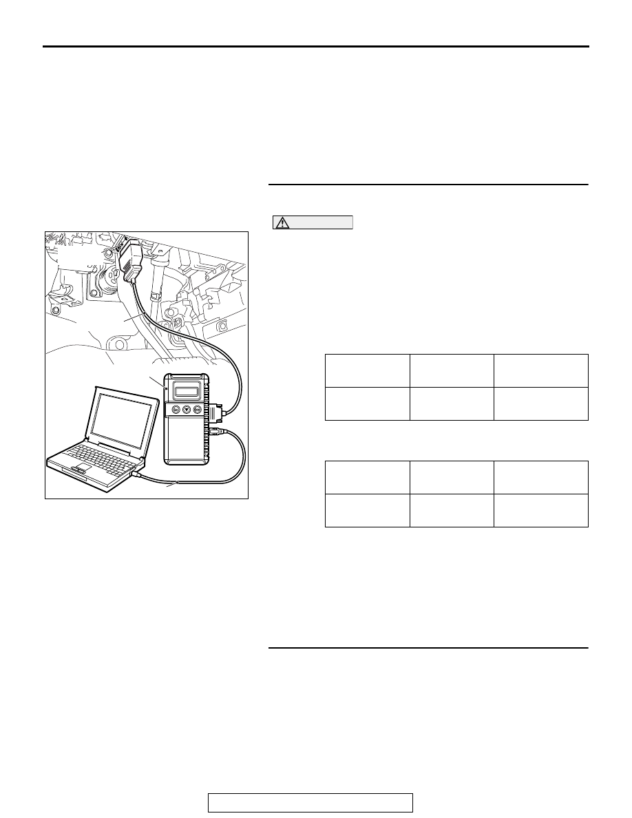
Required Special Tools:

• MB991223: Harness Set

• MB992006: Extra Fine Probe

•  MB991958: Scan Tool (M.U.T.-III Sub Assembly)

• MB991824: Vehicles Communication Interface (V.C.I.)

• MB991827: M.U.T.-III USB Cable

• MB991910: M.U.T.-III Main Harness A

STEP 1. Using scan tool MB991958, check data list.
Check the input signals from the front door lock actuators.

CAUTION

To prevent damage to scan tool MB991958, always turn the 
ignition switch to the "LOCK" (OFF) position before con-
necting or disconnecting scan tool MB991958.
(1) Connect scan tool MB991958. Refer to GROUP 42B, 

Diagnosis "How to connect the Scan Tool (M.U.T.-III) 

P.42B-13

."

(2) Turn the ignition switch to the "ON" position.
(3) Check the ETACS data list.

• Set the driver's door to "UNLOCK."

• Set the front passenger's door to "UNLOCK." <Vehicles 

with KOS>

(4) Turn the ignition switch to the "LOCK" (OFF) position.
Q: Are normal conditions displayed on the "Dr door unlock 

switch" and "As door unlock switch"?
YES : 
Go to Step 2.
NO :  Refer to GROUP 54A, Inspection Procedure 4: 

ETACS-ECU does not receive any signal from the 
front door lock actuator 

P.54A-794

.

STEP 2. Check ETACS-ECU connector C-309 for loose, 
corroded or damaged terminals, or terminals pushed back 
in the connector.
Q: Is ETACS-ECU connector C-309 in good condition?

YES : Go to Step 3.
NO :  Repair or replace the damaged component(s). Refer 

to GROUP 00E, Harness Connector Inspection 

P.00E-2

. Verify that the central door locking system 

works normally.

Item No.

Item name

Normal 
condition

Item 271

Dr door unlock 
switch

Unlock

Item No.

Item name

Normal 
condition

Item 272

As door unlock 
switch

Unlock

ZC501967

AC404789

AC701411AB

MB991824

MB991827

MB991910

Data link 
connector

DOOR

TSB Revision

BODY

42A-40

STEP 3. Check the wiring harness between ETACS-ECU 
connector C-309 (terminal 2) and fusible link (37).

• Check the power supply line for open circuit and short cir-

cuit.

Q: Is the wiring harness between ETACS-ECU connector 

C-309 (terminal 2) and fusible link (37) in good 
condition?
YES : 
Go to Step 4.
NO :  The wiring harness may be damaged or the connector 

may have loose, corroded or damaged terminals, or 
terminals pushed back in the connector. Repair the 
wiring harness as necessary. Verify that the central 
door locking system works normally.

STEP 4. Retest the system.
Check that the central door locking system works normally.
Q: Is the check result normal?

YES : No action is necessary and testing is complete.
NO :  Replace the ETACS-ECU. Check that the central door 

locking system works normally.

DOOR

TSB Revision

BODY

42A-41

INSPECTION PROCEDURE A-2: Central Door Locking System does not Operate even when Door 
Lock Switch of Power Window Main Switch Operated (Door Lock Switch of Front Power Window Sub 
Switch Operates Normally).

CAUTION

Before replacing the ECU, ensure that the power 
supply circuit, the ground circuit and the com-
munication circuit are normal.

AC901315

FUSIBLE
LINK

37

DOOR
LOCK
RELAY

DRIVER'S
DOOR
UNLOCK
RELAY

PASSENGER'S
DOOR
UNLOCK
RELAY

LIFTGATE
LOCK
RELAY

Central Door Lock Power Supply Circuit

FRONT DOOR LOCK ACTUATOR OR

REAR DOOR LOCK ACTUATOR

FRONT DOOR LOCK ACTUATOR, 

REAR DOOR LOCK ACTUATOR OR 

LIFTGATE LOCK ACTUATOR

ETACS-ECU

RED

RED

FRONT POWER 
WINDOW 
SUB SWITCH

POWER WINDOW 
MAIN SWITCH

DOOR 
LOCK 
SWITCH

DOOR 
LOCK 
SWITCH

BLACK

WHITE-

BLACK

WHITE-

BLACK

WHITE-

BLACK

RED- YELLOW

RED- YELLOW

RED- WHITE

GREEN-

WHITE

GREEN-

WHITE

RED- YELLOW

VIOLET

AC

BLACK

BLACK

BLACK

BLACK

BLACK

BLACK

DOOR

TSB Revision

BODY

42A-42

.

CIRCUIT OPERATION

• The ETACS-ECU controls the central door lock-

ing system, locking or unlocking all doors by acti-
vating the central door lock relay (built into the 
ETACS-ECU). The ETACS-ECU uses inputs from 
the following components:

• Door lock actuators

• Door lock switch, which is incorporated in the 

power window main switch or front power win-
dow sub switch

.

TROUBLESHOOTING HINTS

• The wiring harness or connectors may have 

loose, corroded, or damaged terminals, or termi-
nals pushed back in the connector

• The power window main switch may be defective

DIAGNOSTIC PROCEDURE

STEP 1. Checking central door unlocking operation
Check that the central door locking system works normally.
Q: Is the check result normal?

YES : Go to Step 2.
NO :  Refer to Inspection procedure A-1 "Central door 

locking system does not work at all 

P.42A-38

."

STEP 2. Check power window main switch connector E-19 
for loose, corroded or damaged terminals, or terminals 
pushed back in the connector.
Q: Is power window main switch connector E-19 in good 

condition?
YES : 
Go to Step 3.
NO :  Repair or check the connector. Refer to GROUP 00E, 

Harness Connector Inspection 

P.00E-2

. Verify that all 

the doors can be locked and unlocked normally.

AC701918AC

Connector: C-127

C-127 (BR)

ACA01378

AR

C-301

C-315

Connectors: C-301,  C-315

ETACS-ECU

AC702763

Connector: E-19

AE


Content   ..  1057  1058  1059  1060   ..