Mitsubishi Outlander GS45X. Manual - part 1024


  Index      Mitsubishi     Mitsubishi Outlander GS45X - service repair manual


Search            


Content   ..  1022  1023  1024  1025   ..


Mitsubishi Outlander GS45X. Manual - part 1024


AMBIENT AIR TEMPERATURE SENSOR

TSB Revision

HEATER, AIR CONDITIONING AND VENTILATION

55A-123

AMBIENT AIR TEMPERATURE SENSOR

REMOVAL AND INSTALLATION

M1554017500131

INSPECTION

M1551006300781

.

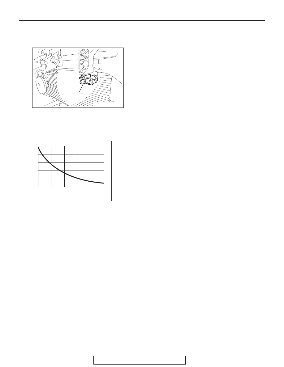
AMBIENT AIR TEMPERATURE SENSOR CHECK

Measure the resistance between the sensor terminals under at 
least two temperatures. The resistance values should meet the 
values shown.
NOTE: The temperature should be within the shown range.

AC900828

1

AC

Removal steps 

Front bumper (Refer to GROUP 51, 
Front bumper assembly 

P.51-4

)

1.

Ambient air temperature sensor

AC209192

10

8

6

4

2

0

AB

10
(50)

30
(86)

Resistance

(k

Ω)

Temperature ºC (ºF)

  0
(32)

  40
(104)

-10
(14)

 20
(68)

A/C-ECU

TSB Revision

HEATER, AIR CONDITIONING AND VENTILATION

55A-124

A/C-ECU

REMOVAL AND INSTALLATION

M1554016600298

Pre-removal and Post-installation Operation
• Glove Box and Bottom Cover Assembly (passenger's 

side) Removal and Installation (Refer to GROUP 52A 

− 

Instrument Panel 

P.52A-2

).

• Foot duct Removal and Installation (Refer to 

P.55A-135

).

AC708793

A/C-ECU

AC

COMPRESSOR ASSEMBLY

TSB Revision

HEATER, AIR CONDITIONING AND VENTILATION

55A-125

COMPRESSOR ASSEMBLY

REMOVAL AND INSTALLATION

M1552004402651

NOTE: The service points which are not described 
are the same as before.

Pre-removal Operation
• Refrigerant Discharging (Refer to 

P.55A-108

).

• Front bumper under cover (Refer to GROUP 51, Front 

bumper 

P.51-4

).

• Front under cover RH (Refer to GROUP 51, Under cover 

P.51-22

).

• Drive belt removal (Refer to GROUP 11A, Crankshaft pul-

ley 

P.11A-21

) <2.4L>

• Drive belt removal (Refer to GROUP 11C, Crankshaft pul-

ley 

P.11C-23

) <3.0L>

Post-installation Operation
• Drive belt installation (Refer to GROUP 11A, Crankshaft 

pulley 

P.11A-21

) <2.4L>

• Drive belt installation (Refer to GROUP 11C, Crankshaft 

pulley 

P.11C-23

) <3.0L>

• Drive belt tension adjustment (Refer to GROUP 11A, 

On-vehicles service 

− Drive belt tension chec

P.11A-9

). 

<2.4L>

• Drive belt tension adjustment (Refer to GROUP 11C, 

On-vehicles service 

− Generator drive belt tension check 

P.11C-8

). <3.0L>

• Refrigerant Charging (Refer to 

P.55A-108

).

• Front bumper under cover (Refer to GROUP 51, Front 

bumper 

P.51-4

).

• Front under cover RH (Refer to GROUP 51, Under cover 

P.51-22

).

AC800691

1, 2

3

5

3

2

1

4

AD

N

10 ± 2 N·m
89 ± 17 in-lb

23 ± 6 N·m
17 ± 4 ft-lb

-Pipe coupling

10 ± 2 N·m
89 ± 17 in-lb

23 ± 6 N·m
17 ± 4 ft-lb

23 ± 6 N·m
17 ± 4 ft-lb

23 ± 6 N·m
17 ± 4 ft-lb

6

A/C compressor oil: 
SUN PAG 56 or S10X

5

<2.4 L>

<3.0 L>

Removal steps 

<<

A

>>

1.

Flexible suction hose connection

<<

A

>>

2.

Flexible discharge hose connection

3.

O-ring

<<

B

>>

>>

A

<<

4.

A/C compressor and clutch 
assembly

5.

A/C compressor bracket A

6.

A/C compressor bracket B

Removal steps (Continued)

COMPRESSOR ASSEMBLY

TSB Revision

HEATER, AIR CONDITIONING AND VENTILATION

55A-126

REMOVAL SERVICE POINTS

.

<<A>> FLEXIBLE DISCHARGE HOSE / FLEXIBLE 
SUCTION HOSE DISCONNECTION

CAUTION

As the compressor oil and receiver are highly moisture 
absorbent, use a non-porous material to plug the hose and 
nipples.
To prevent the entry of dust or other foreign bodies, plug the 
dismantled hoses and compressor nipples.

.

<<B>> A/C COMPRESSOR REMOVAL

Take care not to spill any compressor oil when removing the 
compressor.

INSTALLATION SERVICE POINT

.

>>A<< A/C COMPRESSOR AND CLUTCH ASSEM-
BLY INSTALLATION

If a new compressor is installed, first adjust the amount of oil 
according to the procedures described below, and then install 
the compressor.
1. Measure the amount [X cm

3

 (X fl.oz) of oil within the 

removed compressor.

2. Drain (from the new compressor) the amount of oil 

calculated according to the following formula, and then 
install the new compressor.
New compressor oil amount = 70cm

(2.4 fl.oz)

70 cm

3


 X cm

3

 = Y cm

3

 (2.4 fl.oz. 

 X fl.oz. = Y fl.oz)

NOTE: Y cm

3

 (Y fl.oz) indicates the amount of oil in the refrig-

erant line, the condenser, the evaporator, etc.
NOTE: When replacing the following parts at the same times as 
the compressor, subtract the rated oil amount of each part from 
Y cm

3

 (Y fl.oz) and discharge from the new compressor.

3. Tighten A/C compressor and clutch assembly mounting 

bolts to the specified torque in the order of number shown in 
the figure.

Tightening torque: 23 

± 6 Nm

AC506759

AE

1

2

3

A/C compressor 
and clutch assembly


Content   ..  1022  1023  1024  1025   ..