Mitsubishi Outlander (2013+). Manual - part 750
CONDENSER ASSEMBLY
HEATER, AIR CONDITIONER AND VENTILATION
55-56
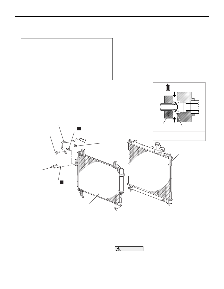
CONDENSER ASSEMBLY
REMOVAL AND INSTALLATION
M1552015401607
Pre-removal and Post-installation Operation
• Discharging and Recharging refrigerant (Refer to
• Air Cleaner Intake Duct (Refer to GROUP 15 − Air
Cleaner ).
• Headlamp support upper panel cover (Refer to GROUP
51, Radiator Grille )
• Hood latch (Refer to GROUP 42A − Hood ).
• Headlamp support panel upper (Refer to GROUP 42A −
Loose Panel ).
ACB03697
1, 4
2, 5
-Pipe coupling
A/C compressor oil:
SUN PAG 56 or S10X
2
1
5
N
N
6
3
4
AB
Radiator assembly
4.9 ± 0.9 N·m
Removal steps
<<
A
>>
>>
A
<<
1.
A/C compressor discharge hose
connection
2.
O-ring
3.
Clamp
<<
A
>>
4.
A/C condenser outlet pipe
connection
5.
O-ring
6.
Condenser assembly
NOTE: Condenser fan removal and installation refer
to GROUP 14
−
Radiator .
REMOVAL SERVICE POINT
<<A>> A/C COMPRESSOR DISCHARGE
HOSE AND A/C CONDENSER OUTLET
PIPE DISCONNECTION
CAUTION
Use the plug which is not breathable because
A/C compressor oil or receiver have high hygro-
scopicity.
Plug the removed nipple of the pipe, hose and con-
denser to prevent the entry of dust and dirt.