Mitsubishi Outlander (2013+). Manual - part 748
AMBIENT TEMPERATURE SENSOR
HEATER, AIR CONDITIONER AND VENTILATION
55-48
INSTALLATION SERVICE POINT
>>A<< OUTSIDE/INSIDE AIR SELECTION
DAMPER CONTROL MOTOR INSTALLA-
TION
Install the outside/inside air selection damper control
motor while pressing the outside/inside air selection
damper from the hole of the blower motor.
>>B<< CLEAN AIR FILTER
INSTALLATION
7803A004
>PP.PET<
helsatech PF087
Made in
XX.XX.XX
XX:XX
AIR FLOW
AC508409
AC
Front view
Install with the arrow
facing down.
Install the clean air filter in the direction shown.
INSPECTION
M1552014305182
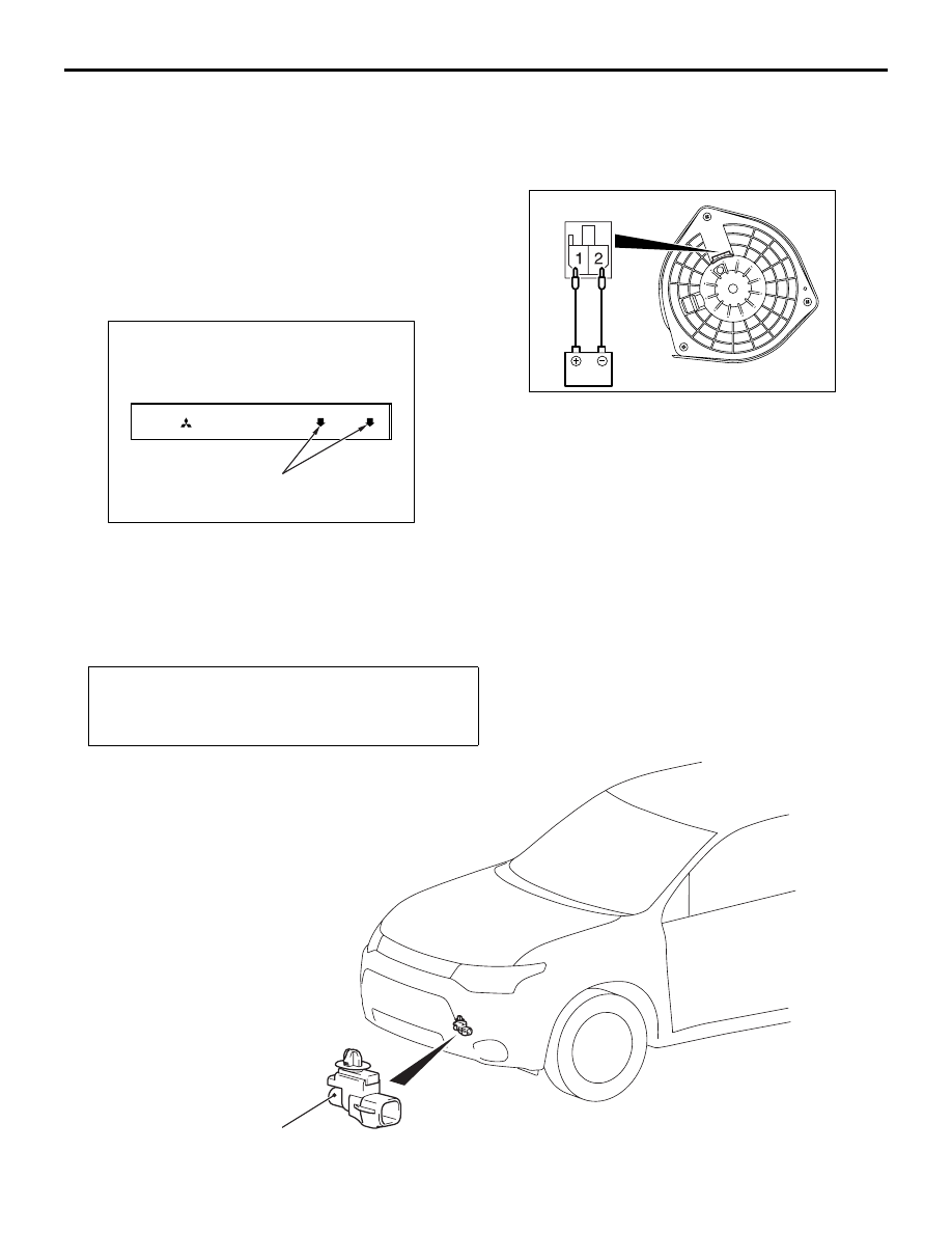
BLOWER MOTOR CHECK
AC611918
AK
Check that the motor turns when applying battery
power between the connector terminals. Also check
to see that there is no abnormal sound emitted from
the motor at this time.
AMBIENT TEMPERATURE SENSOR
REMOVAL AND INSTALLATION
M1554003400915
Pre-removal and Post-installation Operation
• Air cleaner intake duct (Refer to GROUP 15, Air Cleaner )
• Headlamp support upper panel cover (Refer to GROUP
51, Radiator Grille )
ACB04999
1
AB