Mitsubishi Outlander (2013+). Manual - part 747
ACB03694
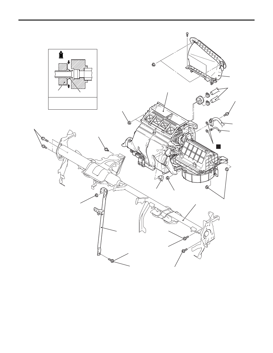
2, 3
A/C compressor oil:
SUN PAG 56 or S10X
-Pipe coupling
4
24 ± 4 N·m
11 ± 4 N·m
AC
1
2
3
4
N
5
7
9
10
11
18 ± 7 N·m
20 ± 5 N·m
20 ± 4 N·m
13 ± 2 N·m
50 ± 5 N·m
11 ± 4 N·m
11 ± 4 N·m
4.9 ± 0.9 N·m
6
8
Removal steps
1.
Heater piping hose connection
<<
A
>>
2.
A/C compressor suction hose
connection
<<
A
>>
3.
A/C condenser outlet pipe
connection
4.
O-ring
5.
A/C evaporator drain hose
•
Instrument panel removal and
Installation (Refer to GROUP 52A,
Instrument Panel ).
•
Instrument panel wiring harness
connector disconnection
6.
Earth bolt
7.
Centre flame assembly
8.
Earth bolt
9.
Front deck crossmember
10. Heater air intake duct
11. Heater assembly
HEATER UNIT AND BLOWER ASSEMBLY
HEATER, AIR CONDITIONER AND VENTILATION
55-44
Removal steps (Continued)