Mitsubishi Outlander (2013+). Manual - part 724
TROUBLESHOOTING
CONTROLLER AREA NETWORK (CAN)
54C-32
YES :
Repair the wiring harness between joint
connector (CAN-HI) and the SRS-ECU
connector.
NO :
Check the SRS-ECU connector, and repair
if necessary. If the SRS-ECU connector is in
good condition, go to Step 22.
STEP 22. M.U.T.-III CAN bus diagnostics (retest
the system)
Diagnose CAN-C, and check if M.U.T.-III screen
shows normal state.
Q: Is the check result normal?
YES :
The trouble can be an intermittent
malfunction (Refer to GROUP 00
− How to
use Troubleshooting/inspection Service
Points
− How to Cope with Intermittent
Malfunction ).
NO :
Check the SRS-ECU connector, and repair
if necessary. If the SRS-ECU connector is in
good condition, replace the SRS-ECU.
STEP 23. Check the CAN-C between joint
connector (CAN-HI) and the diagnosis connector.
Resistance measurement at joint connector
(CAN-HI).
CAUTION
A digital multimeter should be used. For details
refer to
CAUTION
The test wiring harness should be used. For
details refer to
(1) Disconnect joint connector (CAN-HI), and
measure at the wiring harness side.
CAUTION
When measuring the resistance, disconnect the
negative battery terminal. For details refer to
.
(2) Ensure that the negative battery terminal is
disconnected.
(3) Resistance between joint connector (CAN-HI)
terminal No.9 (CAN_H) and body earth
OK: 1 k
Ω or more
(4) Resistance between joint connector (CAN-HI)
terminal No.20 (CAN_L) and body earth
OK: 1 k
Ω or more
CAUTION
Strictly observe the specified wiring harness
repair procedure. For details refer to
Q: Is the check result normal?
YES :
<1 k
Ω or more> Repair the intermediate
connector C-126, or the wiring harness
between joint connector (CAN-HI) and the
intermediate connector C-126.
NO :
<Less than 1 k
Ω > Repair the diagnosis
connector, or the wiring harness between
joint connector (CAN-HI) and the diagnosis
connector.
STEP 24. M.U.T.-III CAN bus diagnostics
[engine-ECU connector disconnected]
(1) Disconnect engine-ECU connector, and diagnose
by using the M.U.T.-III.
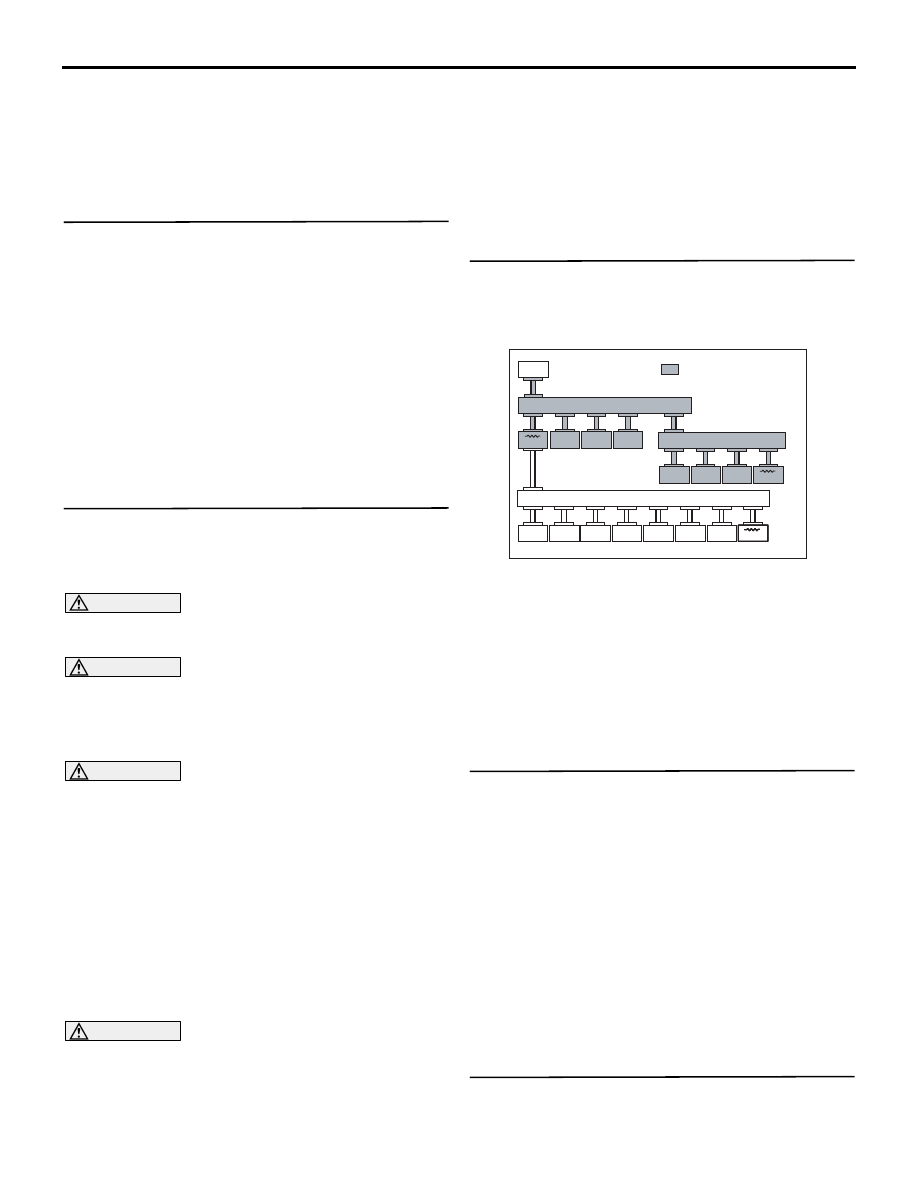
ACC00052
ACC00052
M.U.T.
: Red section on screen
JC
ETACS
KOS
AUDIO
SRS
OSS
ABS/ASC
CVT
ENGINE
EPS
SAS
AWC
MMCS
A/C
ETG
METER
Corner
JC
JC
AB
(2) Diagnose CAN-C, and check if M.U.T.-III screen
is as shown in the illustration.
Q: Does M.U.T.-III screen correspond to the
illustration?
YES :
Go to Step 26.
NO :
Check the engine-ECU connector, and
repair if necessary. If the engine-ECU
connector is in good condition, go to Step
25.
STEP 25. M.U.T.-III CAN bus diagnostics (retest
the system)
Diagnose CAN-C, and check if M.U.T.-III screen
shows normal state.
Q: Is the check result normal?
YES :
The trouble can be an intermittent
malfunction (Refer to GROUP 00
− How to
use Troubleshooting/inspection Service
Points
− How to Cope with Intermittent
Malfunction ).
NO :
Check the engine-ECU connector, and
repair if necessary. If the engine-ECU
connector is in good condition, replace the
engine-ECU.
STEP 26. M.U.T.-III CAN bus diagnostics
[ETACS-ECU connector disconnected]
(1) Disconnect ETACS-ECU connector, and