Mitsubishi Outlander (2013+). Manual - part 723


  Index      Mitsubishi     Mitsubishi Outlander - service repair manual 2013 year


Search            


Content   ..  721  722  723  724   ..


Mitsubishi Outlander (2013+). Manual - part 723


TROUBLESHOOTING

CONTROLLER AREA NETWORK (CAN)

54C-28

STEP 7. Check the CAN line between joint 
connector (CAN1) and the EPS-ECU. Resistance 
measurement at joint connector (CAN1).

CAUTION

A digital multimeter should be used. For details 
refer to 

P.54C-5

.

CAUTION

The test wiring harness should be used. For 
details refer to 

P.54C-5

.

(1) Disconnect joint connector (CAN1), and measure 

at the wiring harness side.

CAUTION

When measuring the resistance, disconnect the 
negative battery terminal. For details refer to 

P.54C-5

.

(2) Ensure that the negative battery terminal is 

disconnected.

(3) Resistance between joint connector (CAN1) 

terminal No.8 (CAN_H) and body earth

OK: 1 k

 or more

(4) Resistance between joint connector (CAN1) 

terminal No.19 (CAN_L) and body earth

OK: 1 k

 or more

Q: Is the check result normal?

YES : 

<1 k

Ω or more> Go to Step 10.

NO : 

<Less than 1 k

Ω > Go to Step 8.

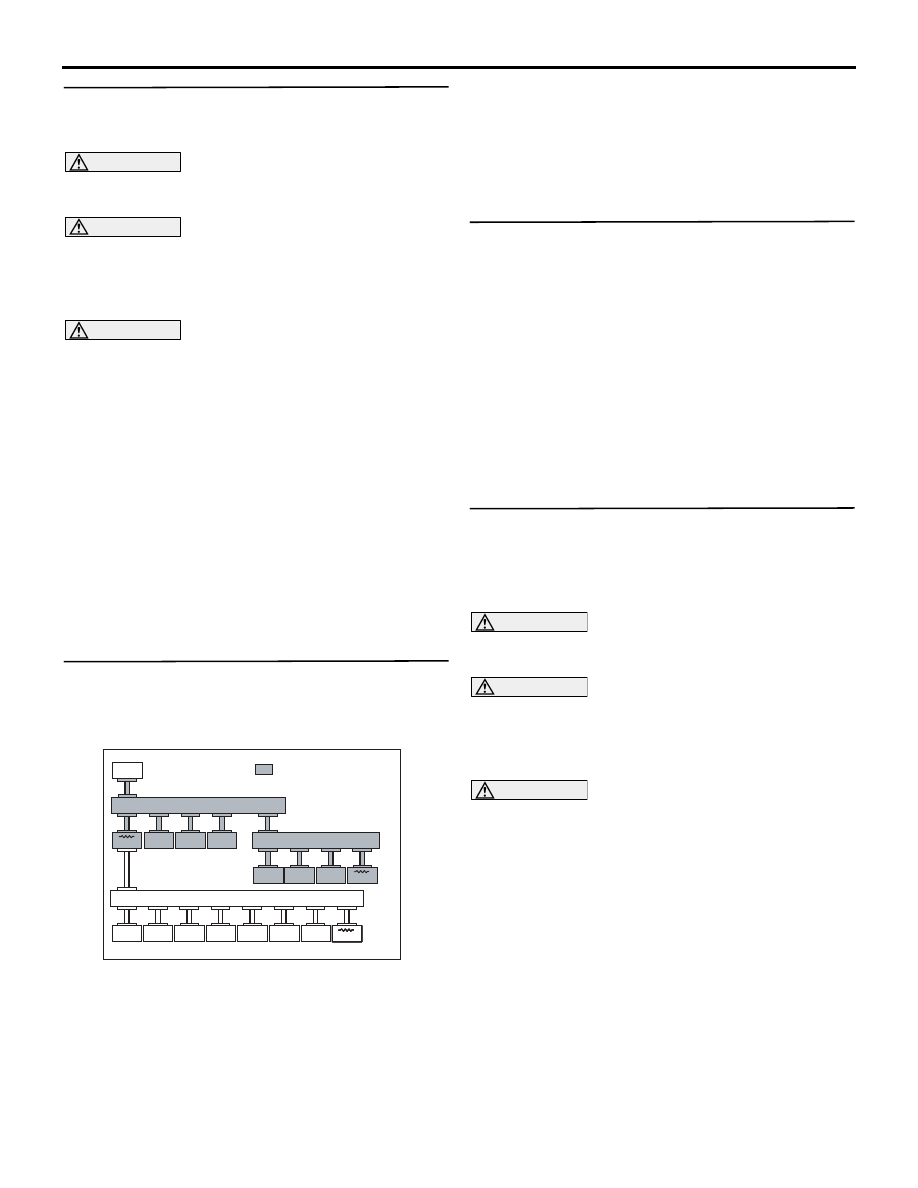
STEP 8. M.U.T.-III CAN bus diagnostics [EPS-ECU 
connector disconnected]
(1) Disconnect EPS-ECU connector, and diagnose 

by using the M.U.T.-III.

ACC00052

ACC00052

M.U.T.

: Red section on screen

JC

ETACS

KOS

AUDIO

SRS

OSS

ABS/ASC

CVT

ENGINE

EPS

SAS

AWC

MMCS

A/C

ETG

METER

Corner

JC

JC

AB

(2) Diagnose CAN-C, and check if M.U.T.-III screen 

is as shown in the illustration.

Q: Does M.U.T.-III screen correspond to the 

illustration?

YES : 

Repair the wiring harness between joint 

connector (CAN1) and the EPS-ECU 
connector.

NO : 

Check the EPS-ECU connector, and repair 
if necessary. If the EPS-ECU connector is in 
good condition, go to Step 9.

STEP 9. M.U.T.-III CAN bus diagnostics (retest the 
system)
Diagnose CAN-C, and check if M.U.T.-III screen 
shows normal state.

Q: Is the check result normal?

YES : 

The trouble can be an intermittent 

malfunction (Refer to GROUP 00 

− How to 

use Troubleshooting/inspection Service 
Points 

− How to Cope with Intermittent 

Malfunction ).

NO : 

Check the EPS-ECU connector, and repair 
if necessary. If the EPS-ECU connector is in 
good condition, replace the EPS-ECU.

STEP 10. Check the CAN-C between joint 
connector (CAN1) and the ABS-ECU <vehicles 
without ASC> or ASC-ECU <vehicles with ASC>. 
Resistance measurement at joint connector 
(CAN1).

CAUTION

A digital multimeter should be used. For details 
refer to 

P.54C-5

.

CAUTION

The test wiring harness should be used. For 
details refer to 

P.54C-5

.

(1) Disconnect joint connector (CAN1), and measure 

at the wiring harness side.

CAUTION

When measuring the resistance, disconnect the 
negative battery terminal. For details refer to 

P.54C-5

.

(2) Ensure that the negative battery terminal is 

disconnected.

(3) Resistance between joint connector (CAN1) 

terminal No.9 (CAN_H) and body earth

OK: 1 k

 or more

(4) Resistance between joint connector (CAN1) 

terminal No.20 (CAN_L) and body earth

OK: 1 k

 or more

Q: Is the check result normal?

TROUBLESHOOTING

CONTROLLER AREA NETWORK (CAN)

54C-29

YES : 

<1 k

Ω or more> Repair intermediate 

connector C-126, or the wiring harness 
between joint connector (CAN1) and 
intermediate connector C-126.

NO : 

<Less than 1 k

Ω > Go to Step 11.

STEP 11. M.U.T.-III CAN bus diagnostics 
[ABS-ECU <vehicles without ASC> or ASC-ECU 
<vehicles with ASC> connector disconnected]
(1) Disconnect ABS-ECU <vehicles without ASC> or 

ASC-ECU <vehicles with ASC> connector, and 
diagnose by using the M.U.T.-III.

ACC00052

ACC00052

M.U.T.

: Red section on screen

JC

ETACS

KOS

AUDIO

SRS

OSS

ABS/ASC

CVT

ENGINE

EPS

SAS

AWC

MMCS

A/C

ETG

METER

Corner

JC

JC

AB

(2) Diagnose CAN-C, and check if M.U.T.-III screen 

is as shown in the illustration.

Q: Does M.U.T.-III screen correspond to the 

illustration?
YES : 

Repair the wiring harness between joint 

connector (CAN1) and the ABS-ECU 
<vehicles without ASC> or ASC-ECU 
<vehicles with ASC> connector.

NO : 

Check the ABS-ECU <vehicles without 
ASC> or ASC-ECU <vehicles with ASC> 
connector, and repair if necessary. If the 
EPS-ECU connector is in good condition, go 
to Step 12.

STEP 12. M.U.T.-III CAN bus diagnostics (retest 
the system)
Diagnose CAN-C, and check if M.U.T.-III screen 
shows normal state.

Q: Is the check result normal?

YES : 

The trouble can be an intermittent 

malfunction (Refer to GROUP 00 

− How to 

use Troubleshooting/inspection Service 
Points 

− How to Cope with Intermittent 

Malfunction ).

NO : 

Check the ABS-ECU <vehicles without 
ASC> or ASC-ECU <vehicles with ASC> 
connector, and repair if necessary. If the 
ABS-ECU <vehicles without ASC> or 
ASC-ECU <vehicles with ASC> connector is 
in good condition, replace the ABS-ECU 
<vehicles without ASC> or ASC-ECU 
<vehicles with ASC>.

STEP 13. Check CAN line between joint 
connector (CAN-HI) and the ETACS-ECU. 
Resistance measurement at joint connector 
(CAN-HI).

CAUTION

A digital multimeter should be used. For details 
refer to 

P.54C-5

.

CAUTION

The test wiring harness should be used. For 
details refer to 

P.54C-5

.

(1) Disconnect joint connector (CAN-HI), and 

measure at the wiring harness side.

CAUTION

When measuring the resistance, disconnect the 
negative battery terminal. For details refer to 

P.54C-5

.

(2) Ensure that the negative battery terminal is 

disconnected.

(3) Resistance between joint connector (CAN-HI) 

terminal No.11 (CAN_H) and body earth

OK: 1 k

 or more

(4) Resistance between joint connector (CAN-HI) 

terminal No.22 (CAN_L) and body earth

OK: 1 k

 or more

CAUTION

Strictly observe the specified wiring harness 
repair procedure. For details refer to 

P.54C-5

.

Q: Is the check result normal?

YES <2WD> : 

<1 k

Ω or more> Go to Step 17.

YES <4WD> : 

<1 k

Ω or more> Go to Step 14.

NO  : 

<Less than 1 k

Ω > Repair the wiring 

harness between joint connector (CAN-HI) 
and the ETACS-ECU connector.

TROUBLESHOOTING

CONTROLLER AREA NETWORK (CAN)

54C-30

STEP 14. Check the CAN-C between joint 
connector (CAN-HI) and the 4WD-ECU. 
Resistance measurement at joint connector 
(CAN-HI).

CAUTION

A digital multimeter should be used. For details 
refer to 

P.54C-5

.

CAUTION

The test wiring harness should be used. For 
details refer to 

P.54C-5

.

(1) Disconnect joint connector (CAN-HI), and 

measure at the wiring harness side.

CAUTION

When measuring the resistance, disconnect the 
negative battery terminal. For details refer to 

P.54C-5

.

(2) Ensure that the negative battery terminal is 

disconnected.

(3) Resistance between joint connector (CAN-HI) 

terminal No.5 (CAN_H) and body earth

OK: 1 k

 or more

(4) Resistance between joint connector (CAN-HI) 

terminal No.16 (CAN_L) and body earth

OK: 1 k

 or more

CAUTION

Strictly observe the specified wiring harness 
repair procedure. For details refer to 

P.54C-5

.

Q: Is the check result normal?

YES : 

<1 k

Ω or more> Go to Step 17.

NO : 

<Less than 1 k

Ω > Go to Step 15.

STEP 15. M.U.T.-III CAN bus diagnostics 
[4WD-ECU connector disconnected]
(1) Disconnect 4WD-ECU connector, and diagnose 

by using the M.U.T.-III.

ACC00052

ACC00052

M.U.T.

: Red section on screen

JC

ETACS

KOS

AUDIO

SRS

OSS

ABS/ASC

CVT

ENGINE

EPS

SAS

AWC

MMCS

A/C

ETG

METER

Corner

JC

JC

AB

(2) Diagnose CAN bus lines, and check if M.U.T.-III 

screen is as shown in the illustration.

Q: Does M.U.T.-III screen correspond to the 

illustration?
YES : 

Check the intermediate connector, and 

repair if necessary. If the intermediate 
connector is in good condition, repair the 
wiring harness between joint connector 
(CAN-HI) and the 4WD-ECU connector.

NO : 

Check the 4WD-ECU connector, and repair 
if necessary. If the 4WD-ECU connector is 
in good condition, go to Step 16.

STEP 16. M.U.T.-III CAN bus diagnostics (retest 
the system)
Diagnose CAN-C, and check if M.U.T.-III screen 
shows normal state.

Q: Is the check result normal?

YES : 

The trouble can be an intermittent 

malfunction (Refer to GROUP 00 

− How to 

use Troubleshooting/inspection Service 
Points 

− How to Cope with Intermittent 

Malfunction ).

NO : 

Check the 4WD-ECU connector, and repair 
if necessary. If the 4WD-ECU connector is 
in good condition, replace the 4WD-ECU.

STEP 17. Check the CAN-C between joint 
connector (CAN-HI) and the steering wheel 
sensor. Resistance measurement at joint 
connector (CAN-HI).

CAUTION

A digital multimeter should be used. For details 
refer to 

P.54C-5

.

CAUTION

The test wiring harness should be used. For 
details refer to 

P.54C-5

.

(1) Disconnect joint connector (CAN-HI), and 

measure at the wiring harness side.

CAUTION

When measuring the resistance, disconnect the 
negative battery terminal. For details refer to 

P.54C-5

.

(2) Ensure that the negative battery terminal is 

disconnected.

(3) Resistance between joint connector (CAN-HI) 

terminal No.6 (CAN_H) and body earth

OK: 1 k

 or more

(4) Resistance between joint connector (CAN-HI) 

TROUBLESHOOTING

CONTROLLER AREA NETWORK (CAN)

54C-31

terminal No.17 (CAN_L) and body earth

OK: 1 k

 or more

CAUTION

Strictly observe the specified wiring harness 
repair procedure. For details refer to 

P.54C-5

.

Q: Is the check result normal?

YES : 

<1 k

Ω or more> Go to Step 20.

NO : 

<Less than 1 k

Ω > Go to Step 18.

STEP 18. M.U.T.-III CAN bus diagnostics [steering 
wheel sensor connector disconnected]
(1) Disconnect steering wheel sensor connector, and 

diagnose by using the M.U.T.-III.

ACC00052

ACC00052

M.U.T.

: Red section on screen

JC

ETACS

KOS

AUDIO

SRS

OSS

ABS/ASC

CVT

ENGINE

EPS

SAS

AWC

MMCS

A/C

ETG

METER

Corner

JC

JC

AB

(2) Diagnose CAN-C, and check if M.U.T.-III screen 

is as shown in the illustration.

Q: Does M.U.T.-III screen correspond to the 

illustration?
YES : 

Repair the wiring harness between joint 

connector (CAN-HI) and the steering wheel 
sensor connector.

NO : 

Check the steering wheel sensor connector, 
and repair if necessary. If the steering wheel 
sensor connector is in good condition, go to 
Step 19.

STEP 19. M.U.T.-III CAN bus diagnostics (retest 
the system)
Diagnose CAN-C, and check if M.U.T.-III screen 
shows normal state.

Q: Is the check result normal?

YES : 

The trouble can be an intermittent 

malfunction (Refer to GROUP 00 

− How to 

use Troubleshooting/inspection Service 
Points 

− How to Cope with Intermittent 

Malfunction ).

NO : 

Check the steering wheel sensor connector, 
and repair if necessary. If the steering wheel 
sensor connector is in good condition, 
replace the steering wheel sensor.

STEP 20. Check the CAN-C between joint 
connector (CAN-HI) and the SRS-ECU. 
Resistance measurement at joint connector 
(CAN-HI).

CAUTION

A digital multimeter should be used. For details 
refer to 

P.54C-5

.

CAUTION

The test wiring harness should be used. For 
details refer to 

P.54C-5

.

(1) Disconnect joint connector (CAN-HI), and 

measure at the wiring harness side.

CAUTION

When measuring the resistance, disconnect the 
negative battery terminal. For details refer to 

P.54C-5

.

(2) Ensure that the negative battery terminal is 

disconnected.

(3) Resistance between joint connector (CAN-HI) 

terminal No.30 (CAN_H) and body earth

OK: 1 k

 or more

(4) Resistance between joint connector (CAN-HI) 

terminal No.29 (CAN_L) and body earth

OK: 1 k

 or more

CAUTION

Strictly observe the specified wiring harness 
repair procedure. For details refer to 

P.54C-5

.

Q: Is the check result normal?

YES : 

<1 k

Ω or more> Go to Step 23.

NO : 

<Less than 1 k

Ω > Go to Step 21.

STEP 21. M.U.T.-III CAN bus diagnostics 
[SRS-ECU connector disconnected]
(1) Disconnect SRS-ECU connector, and diagnose 

by using the M.U.T.-III.

ACC00052

ACC00052

M.U.T.

: Red section on screen

JC

ETACS

KOS

AUDIO

SRS

OSS

ABS/ASC

CVT

ENGINE

EPS

SAS

AWC

MMCS

A/C

ETG

METER

Corner

JC

JC

AB

(2) Diagnose CAN bus lines, and check if M.U.T.-III 

screen is as shown in the illustration.

Q: Does M.U.T.-III screen correspond to the 

illustration?


Content   ..  721  722  723  724   ..