Mitsubishi Outlander (2013+). Manual - part 661


  Index      Mitsubishi     Mitsubishi Outlander - service repair manual 2013 year


Search            


Content   ..  659  660  661  662   ..


Mitsubishi Outlander (2013+). Manual - part 661


HEADLAMP AUTOMATIC LEVELLING SYSTEM

CHASSIS ELECTRICAL

54A-129

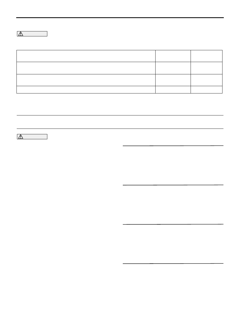
TROUBLE SYMPTOM CHART

M1540301200429

CAUTION

Before or after the troubleshooting, check the operation of the headlamp automatic levelling system. 
Refer to 

P.54A-132

.

Trouble symptom

Inspection 
Procedure No.

Reference 
page

Malfunction of ETACS-ECU power supply circuit.

Refer to 

P.54A-311

.

The both headlamp automatic levelling systems (right and left) do not 
work normally.

1

P.54A-129

One of the automatic levellings does not work.

2

P.54A-130

SYMPTOM PROCEDURES

Inspection Procedure 1: The both headlamp automatic levelling systems (right and left) do not work 
normally. 

CAUTION

• Before replacing the ECU, ensure that the 

power supply circuit, the earth circuit and the 
communication circuit are normal.

• When the ETACS-ECU of vehicles without 

KOS is replaced, the encrypted code of the 
ignition key needs to be registered to the 
ETACS-ECU. (If the encrypted code is not reg-
istered, the engine cannot be started. Regis-
ter the encrypted code as described in 
Immobilizer System 

 How to Register Key ID 

P.54A-33

.)

COMMENTS ON TROUBLE SYMPTOM

If the both headlamp automatic levelling systems 
(right and left) do not work normally, ETACS-ECU ini-
tialization, each height sensor or ETACS-ECU may 
be defective.

PROBABLE CAUSES

• Malfunction of ETACS-ECU initialization

• Malfunction of headlamp assembly (headlamp 

levelling unit)

• Malfunction of  front height sensor

• Malfunction of  rear height sensor

• Malfunction of ETACS-ECU

• Malfunction of CAN bus line

DIAGNOSIS PROCEDURE

STEP 1. M.U.T.-III CAN bus diagnostics
Use the M.U.T.-III to diagnose the CAN bus lines.

Q: Is the check result normal?

YES : 

Go to Step 2.

NO : 

Repair the CAN bus line (Refer to GROUP 
54C 

− Troubleshooting ).

STEP 2. M.U.T.-III other system diagnosis code
Check if diagnosis code is set to the engine-ECU.

Q: Is the diagnosis code set?

YES : 

Troubleshoot the engine (Refer to GROUP 

13A 

− Diagnosis Code Chart .)

NO : 

Go to Step 3.

STEP 3. M.U.T.-III diagnosis code
Check if diagnosis code No. B2513 is set.

Q: Is the diagnosis code set?

YES : 

Perform the troubleshooting of the 

diagnosis code No. B2513.

NO : 

Go to Step 4.

STEP 4. Height sensor installation status check
Check that the front and rear height sensor is 
installed properly.

Q: Is the check result normal?

YES : 

Go to Step 5.

NO : 

Install the height sensor properly.

HEADLAMP AUTOMATIC LEVELLING SYSTEM

CHASSIS ELECTRICAL

54A-130

STEP 5. Retest the system
After the ETCAS-ECU initialization (refer to 

P.54A-131

), check that the headlamp automatic lev-

elling system operates normally.

Q: Is the check result normal?

YES : 

This diagnosis is complete.

NO : 

Go to Step 6.

STEP 6. Front height sensor check
Check the front height sensor with the rear height 
sensor removed.
(1) Disconnect the rear height sensor connector.
(2) Check that the front height sensor is normal 

(Refer to 

P.54A-133

).

Q: Is the check result normal?

YES : 

Go to Step 7.

NO : 

Replace the front height sensor.

STEP 7. Rear height sensor check
Check that the rear height sensor is normal (Refer to 

P.54A-133

).

Q: Is the check result normal?

YES : 

Go to Step 8.

NO : 

Replace the rear height sensor.

STEP 8. Retest the system
Check that the automatic levelling operates normally.

Q: Is the check result normal?

YES : 

The trouble can be an intermittent 

malfunction (Refer to GROUP 00 

− How to 

use Troubleshooting/inspection Service 
Points 

− How to Cope with Intermittent 

Malfunction ).

NO : 

Replace the ETACS-ECU.

Inspection Procedure 2: One of the automatic levellings does not work.

CAUTION

• Before replacing the ECU, ensure that the 

power supply circuit, the earth circuit and the 
communication circuit are normal.

• When the ETACS-ECU of vehicles without 

KOS is replaced, the encrypted code of the 
ignition key needs to be registered to the 
ETACS-ECU. (If the encrypted code is not reg-
istered, the engine cannot be started. Regis-
ter the encrypted code as described in 
Immobilizer System 

 How to Register Key ID 

P.54A-33

.)

COMMENTS ON TROUBLE SYMPTOM

When one of the automatic levellings does not work, 
the wiring harness and connector(s) between the 
ETACS-ECU and the headlamp assembly (head-
lamp levelling unit) may have a problem.

PROBABLE CAUSES

• Malfunction of headlamp assembly (headlamp 

levelling unit)

• Malfunction of ETACS-ECU

• Damaged harness wires and connectors

DIAGNOSIS PROCEDURE

STEP 1. Headlamp levelling unit check
Perform a levelling motor drive test of the headlamp 
levelling unit to check that the motor is driven. Refer 
to .

Q: Is the check result normal?

YES : 

The trouble can be an intermittent 

malfunction (Refer to GROUP 00 

− How to 

Use Troubleshooting/Inspection Service 
Points 

− How to Cope with Intermittent 

Malfunctions ).

NO (The left levelling motor is not driven.) : 

Go to 

Step 2.

NO (The right levelling motor is not driven.) : 

Go to 

Step 5.

STEP 2. Check of open circuit in (MBL, MGL, 
MSL) line between ETACS-ECU connector and 
headlamp assembly (LH) connector.

Q: Is the check result normal?

YES : 

Go to Step 3.

NO : 

Repair the connector(s) or wiring harness.

STEP 3. M.U.T.-III data list
(1) Disconnect the headlamp assembly (LH) and 

(RH) connector.

(2) Turn the ignition switch from "LOCK" (OFF) 

HEADLAMP AUTOMATIC LEVELLING SYSTEM

CHASSIS ELECTRICAL

54A-131

position to "ON" position.

Item No.

Item name

Normal 
condition

Item 418

A/L actuator 
output voltage

Indicates the 
voltage value of 
system voltage 
within the range 
of 20 to 80%.

OK: Normal condition is displayed.

Q: Is the check result normal?

YES : 

Go to Step 4.

NO : 

Go to Step 8.

STEP 4. Check the headlamp assembly (LH).
Check the headlamp assembly (LH) for internal fail-
ure.
(1) Disconnect the headlamp assembly (RH) 

connector.

(2) Turn the ignition switch from "LOCK" (OFF) 

position to "ON" position.

(3) Perform the drive test using the M.U.T.-III. Refer 

to 

P.54A-132

.

Q: Is the check result normal?

YES : 

Go to Step 8.

NO : 

Replace the headlamp assembly (LH).

STEP 5. Check of short to power supply, short to 
earth, and open circuit in (MBR, MGR, MSR) line 
between ETACS-ECU connector and headlamp 
assembly (RH) connector.

Q: Is the check result normal?

YES : 

Go to Step 6.

NO : 

Repair the connector(s) or wiring harness.

STEP 6. M.U.T.-III data list
(1) Disconnect the headlamp assembly (LH) and 

(RH) connector.

(2) Turn the ignition switch from "LOCK" (OFF) 

position to "ON" position.

Item No.

Item name

Normal 
condition

Item 418

A/L actuator 
output voltage

Indicates the 
voltage value of 
system voltage 
within the range 
of 20 to 80%.

OK: Normal condition is displayed.

Q: Is the check result normal?

YES : 

Go to Step 7.

NO : 

Go to Step 8.

STEP 7. Check the headlamp assembly (RH).
Check the headlamp assembly (RH) for internal fail-
ure.
(1) Disconnect the headlamp assembly (LH) 

connector.

(2) Turn the ignition switch from "LOCK" (OFF) 

position to "ON" position.

(3) Perform the drive test using the M.U.T.-III. Refer 

to 

P.54A-132

.

Q: Is the check result normal?

YES : 

Go to Step 8.

NO : 

Replace the headlamp assembly (RH).

STEP 8. Retest the system
Check that the automatic levelling of the right head-
lamp operates normally.

Q: Is the check result normal?

YES : 

The trouble can be an intermittent 

malfunction (Refer to GROUP 00 

− How to 

Use Troubleshooting/Inspection Service 
Points 

− How to Cope with Intermittent 

Malfunction ).

NO : 

Replace the ETACS-ECU.

ON-VEHICLE SERVICE

INITIALISATION OF ETACS-ECU

M1540303300206

After the operation below is completed, initialise the 
ETACS-ECU.

• The ETACS-ECU is replaced.

• The front height sensor is replaced or 

removed/installed.

• The rear height sensor is replaced or 

removed/installed.

• The suspension related components are replaced 

or removed/installed.

INITIALISATION PROCEDURE

Before the initialisation operation, check that the 
diagnosis code No. B2215, B2514, B2515, B2516, 
U0331 is not set to the ETACS-ECU. If it is set, per-
form the troubleshooting before the initialisation. 
(Refer to 

P.54A-122

.)

1. Park the vehicle on a level surface.

HEADLAMP AUTOMATIC LEVELLING SYSTEM

CHASSIS ELECTRICAL

54A-132

2. If the fuel tank is not filled up, put weight in the 

luggage compartment to make up for the fuel 
shortage so that the weight will become 90% of 
full-state weight or heavier. (0.8 kg per litter)

3. There should be no other load in the vehicle other 

than driver or substituted weight of approximately 
75 kg placed in driver's position.

4. Connect the M.U.T.-III to the diagnosis connector 

(For how to connect the M.U.T.-III, refer to 
GROUP 00 

− Diagnosis function ).

5. Turn the ignition switch to "ON" position. (Do not 

start up the engine.)

6. Select the M.U.T.-III screen menu as follows.

(1) Select "ETACS" displayed on the "System 

selection" screen.

(2) Select "Special function."
(3) Select "HS initial position learning."

7. The ETACS-ECU initialisation is completed.

8. Repeat the procedure if a diagnosis code is set by 

turning the ignition switch from "LOCK (OFF)" to 
"ON" again.

9. Perform the headlamp aiming (Refer to Headlamp 

Aiming 

P.54A-111

.)

OPERATION CHECK OF HEADLAMP AUTOMATIC LEVELLING

M1540303400117

With this inspection, it is simply checked that the 
headlamp automatic levelling motor incorporated in 
the headlamp assembly moves in accordance with 
the vehicle posture.

INSPECTION PROCEDURE

1. Park the vehicle on a level surface.

2. Turn the ignition switch to "ON" position. (Do not 

start up the engine.)

3. At the front or rear jack up point, raise the front 

wheels or rear wheels off the earth.

4. Turn ON the headlamp switch.

5. When the front wheels are raised, the upward 

headlamp beam is controlled with the control 
value applicable to the present vehicle posture, 
and the headlamp beam moves downward.

6. When the rear wheels are raised, the downward 

headlamp beam is controlled with the control 
value applicable to the present vehicle posture, 
and the headlamp beam moves upward.

HEADLAMP AUTOMATIC LEVELLING MOTOR DRIVE TEST

M1540302100425

With this inspection, the headlamp automatic level-
ling motor incorporated in the headlamp assembly is 
forcibly activated and checking the motor for normal 
operation is possible.

DRIVE TEST PROCEDURE (WHEN THE 
M.U.T.-III IS USED)

1. Connect the M.U.T.-III to the diagnosis connector 

(For how to connect the M.U.T.-III, refer to 
GROUP 00 

− Diagnosis function ).

2. Turn the ignition switch to "ON" position. (Do not 

start up the engine.)

3. Turn ON the headlamp switch.

4. Select the M.U.T.-III screen menu as follows.

(1) Select "ETACS" displayed on the "System 

selection" screen.

(2) Select "Actuator test."
(3) Select "A/L actuator."
(4) The headlamp beam moves downward if 

"20%" is set for the "Value select" and upward 
if "80%" is set for the "Value select".

5. The drive test is completed.

DRIVE TEST PROCEDURE (WHEN THE 
M.U.T.-III IS NOT USED)

1. Turn the hazard warning lamp switch to the ON 

position.

2. Within 10 seconds after turning the ignition switch 

from OFF to the ON position (do not start up the 
engine), turn the headlamp switch from OFF to 
ON 5 times repeatedly. If you fail to do this, turn 
the ignition switch to OFF once and repeat from 
the beginning.

3. Within 30 seconds after you complete the step 

above successfully, turn off the hazard warning 
lamp switch.

4. The headlamp beam moves downward for 

approximately 3 seconds and upward for 3 
seconds. Then the beam returns to the position 
applicable to the present vehicle posture.

5. The drive test is completed.


Content   ..  659  660  661  662   ..