Mitsubishi Outlander (2013+). Manual - part 659
 

  Index      Mitsubishi     Mitsubishi Outlander - service repair manual 2013 year


Search            


Content   ..  657  658  659  660   ..


Mitsubishi Outlander (2013+). Manual - part 659


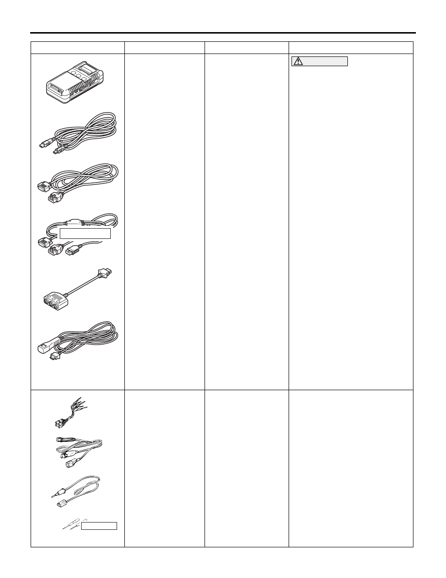
MB991910

MB991826

MB991955

MB991911

MB991824

MB991827

MB991825

a

b

c

d

e

f

DO NOT USE

HEADLAMP AUTOMATIC LEVELLING SYSTEM

CHASSIS ELECTRICAL

54A-121

MB991955

a. MB991824
b. MB991827
c. MB991910
d. MB991911
e. MB991825
f. MB991826

M.U.T.-III 
sub-assembly

a. Vehicle 

Communication 
Interface (V.C.I.)

b. M.U.T.-III USB 

cable

c. M.U.T.-III main 

harness A 
(Vehicles with CAN 
communication 
system)

d. M.U.T.-III main 

harness B 
(Vehicles without 
CAN 
communication 
system)

e. M.U.T.-III measure 

adapter

f. M.U.T.-III trigger 

harness

CAUTION

For vehicles with CAN 
communication, use M.U.T.-III 
main harness A to send 
simulated vehicle speed. If you 
connect M.U.T.-III main harness 
B instead, the CAN 
communication does not 
function correctly.
Diagnosis code check.

MB991223

a

d

c

b

DO NOT USE

BA

MB991223

a. MB991219
b. MB991220
c. MB991221
d. MB991222

Harness set

a. Check harness
b. LED harness
c. LED harness 

adapter

d. Probe

Continuity check and voltage 
measurement at harness wire or 
connector

a. For checking connector pin 

contact pressure

b. For checking power supply 

circuit

c. For checking power supply 

circuit

d. For connecting a locally 

sourced tester

Tool

Number

Name

Use

MB992006

HEADLAMP AUTOMATIC LEVELLING SYSTEM

CHASSIS ELECTRICAL

54A-122

DIAGNOSIS CODE CHART

M1540300500449

CAUTION

• On troubleshooting, if the ignition switch is turned ON while disconnecting connector(s), diagno-

sis code(s) associated with other system may be set. On completion, confirm all systems for diag-
nosis code(s). If diagnosis code(s) are set, erase them all.

• Before or after the troubleshooting, check the operation of the headlamp automatic levelling sys-

tem. Refer to 

P.54A-132

.

Diagnosis 
code No.

Diagnostic item

Reference page

B2215

ECU internal error (EEPROM)

Refer to Diagnosis code 
chart 

P.54A-281

.

B222C

Coding not completed

B2510

Height Sensor Not Initialized

P.54A-123

B2513

Levelling actuator output voltage

P.54A-124

B2514

Height sensor supply voltage

P.54A-125

B2515

Front height sensor signal

P.54A-126

B2516

Rear height sensor signal

P.54A-127

U0100

Engine CAN timeout

Refer to Diagnosis code 
chart 

P.54A-281

.

U0121

ABS/ASC CAN timeout

U0155

Meter CAN timeout

U0331

ECU internal error (ROM)

MB992006

Extra fine probe

Continuity check and voltage 
measurement at harness wire or 
connector

MB991658

MB991658

Test harness

Height sensor check

Tool

Number

Name

Use

HEADLAMP AUTOMATIC LEVELLING SYSTEM

CHASSIS ELECTRICAL

54A-123

DIAGNOSIS CODE PROCEDURES

Code No. B2510 Height Sensor Not Initialized

CAUTION

• If there is any problem in the CAN bus lines, 

an incorrect diagnosis code may be set. Prior 
to this diagnosis, always diagnose the CAN 
bus lines.

• Before replacing the ECU, ensure that the 

power supply circuit, the earth circuit and the 
communication circuit are normal.

• When the ETACS-ECU of vehicles without 

KOS is replaced, the encrypted code of the 
ignition key needs to be registered to the 
ETACS-ECU. (If the encrypted code is not reg-
istered, the engine cannot be started. Regis-
ter the encrypted code as described in 
Immobilizer System 

 How to Register Key ID 

P.54A-33

.)

DIAGNOSTIC FUNCTION

When the headlamp automatic levelling system ini-

tialization 

*

 is not implemented, the code No. B2510 

is stored. When the headlamp automatic levelling 
system initialization is completed, the code No. 
B2510 is cleared automatically.

NOTE: 

*

: When the height sensor related diagnosis 

code (B2514, B2515 or B2516) or ETACS-ECU 
related diagnosis code (B2215 or U0331) is set, ini-
tialization of the headlamp automatic levelling sys-
tem is impossible, therefore perform the 
troubleshooting for the diagnosis code that has been 
set previously.

JUDGEMENT CRITERIA

Initialization of the headlamp automatic levelling sys-
tem is not completed.

PROBABLE CAUSES

• Headlamp automatic levelling system initializa-

tion not completed

• Malfunction of the ETACS-ECU

DIAGNOSIS PROCEDURE

STEP 1. M.U.T.-III CAN bus diagnostics
Use the M.U.T.-III to diagnose the CAN bus lines.

Q: Is the check result normal?

YES : 

Go to Step 2.

NO : 

Repair the CAN bus line (Refer to GROUP 
54C 

− Troubleshooting ).

STEP 2. M.U.T.-III diagnosis code
Check if the height sensor related diagnosis code 
(B2514, B2515 or B2516) or the ETACS-ECU related 
diagnosis code (B2215 or U0331) is set.

Q: Is the diagnosis code set?

YES : 

Perform the troubleshooting of the 

diagnosis code that has been set previously.

NO : 

Go to Step 3.

STEP 3. Check whether the diagnosis code is 
reset.
Initialise the headlamp automatic levelling system 
and check the diagnosis code of the ETACS-ECU.
(1) Turn the ignition switch from "LOCK" (OFF) 

position to "ON" position.

(2) Initialise the headlamp automatic levelling 

system. Refer to 

P.54A-131

.

(3) Check if diagnosis code is set.

Q: Is the diagnosis code set?

YES : 

Replace the ETACS-ECU.

NO : 

The trouble can be an intermittent 
malfunction (Refer to GROUP 00 

− How to 

use Troubleshooting/inspection Service 
Points 

− How to Cope with Intermittent 

Malfunction ).

HEADLAMP AUTOMATIC LEVELLING SYSTEM

CHASSIS ELECTRICAL

54A-124

Code No. B2513 Levelling actuator output voltage

CAUTION

• Before replacing the ECU, ensure that the 

power supply circuit, the earth circuit and the 
communication circuit are normal.

• When the ETACS-ECU of vehicles without 

KOS is replaced, the encrypted code of the 
ignition key needs to be registered to the 
ETACS-ECU. (If the encrypted code is not reg-
istered, the engine cannot be started. Regis-
ter the encrypted code as described in 
Immobilizer System 

 How to Register Key ID 

P.54A-33

.)

DIAGNOSTIC FUNCTION

If a trouble occurs in headlamp assembly (headlamp 
levelling unit), code No. B2513 is stored.

JUDGEMENT CRITERIA

The ETACS-ECU detects the short-circuit of the sig-
nal line to the headlamp assembly (headlamp level-
ling unit) for 1 second or longer continuously.

PROBABLE CAUSES

• Malfunction of headlamp assembly (headlamp 

levelling unit)

• Malfunction of the ETACS-ECU

• Damaged harness wires and connectors

DIAGNOSIS PROCEDURE

STEP 1. Check of short to power supply, short to 
earth circuit in MSL line between headlamp 
assembly (LH) connector and ETACS-ECU 
connector.

Q: Is the check result normal?

YES : 

Go to Step 2.

NO : 

Repair the connector(s) or wiring harness.

STEP 2. Check whether the diagnosis code is 
reset.

Q: Is diagnosis code No. B2513 set?

YES : 

Go to Step 3.

NO : 

The trouble can be an intermittent 
malfunction (Refer to GROUP 00 

− How to 

use Troubleshooting/inspection Service 
Points 

− How to cope with Intermittent 

Malfunction ).

STEP 3. Check of short to power supply, short to 
earth circuit in MSR line between headlamp 
assembly (RH) connector and ETACS-ECU 
connector.

Q: Is the check result normal?

YES : 

Go to Step 4.

NO : 

Repair the connector(s) or wiring harness.

STEP 4. Check whether the diagnosis code is 
reset.

Q: Is diagnosis code No. B2513 set?

YES : 

Go to Step 5.

NO : 

The trouble can be an intermittent 
malfunction (Refer to GROUP 00 

− How to 

use Troubleshooting/inspection Service 
Points 

− How to cope with Intermittent 

Malfunction ).

STEP 5. M.U.T.-III data list
(1) Disconnect the headlamp assembly (LH) and 

headlamp assembly (RH) connector.

(2) Turn the ignition switch from "LOCK" (OFF) 

position to "ON" position.

Item No.

Item name

Normal 
condition

Item 418

A/L actuator 
output voltage

Indicates the 
voltage value of 
system voltage 
within the range 
of 20 to 80%.

OK: Normal condition is displayed.

Q: Is the check result normal?

YES : 

Go to Step 6.

NO : 

Go to Step 8.

STEP 6. Check the headlamp assembly (LH).
Check the headlamp assembly (LH) for internal fail-
ure.
(1) Disconnect the headlamp assembly (RH) 

connector.

(2) Turn the ignition switch from "LOCK" (OFF) 

position to "ON" position.

(3) Perform the drive test using the M.U.T.-III. Refer 

to 

P.54A-132

.

Q: Is the check result normal?

YES : 

Go to Step 7.

NO : 

Replace the headlamp assembly (LH).


Content   ..  657  658  659  660   ..