Mitsubishi Outlander (2013+). Manual - part 592
TROUBLESHOOTING
SUPPLEMENTAL RESTRAINT SYSTEM (SRS)
52B-19
lever, and disconnect the SRS-ECU connector.
CAUTION
To release SRS-ECU connector short spring in
the following operations, disconnect this clock
spring connector, and keep the squib circuit
shorted.
(3) Disconnect the clock spring connector.
AC905150 AO
A
A
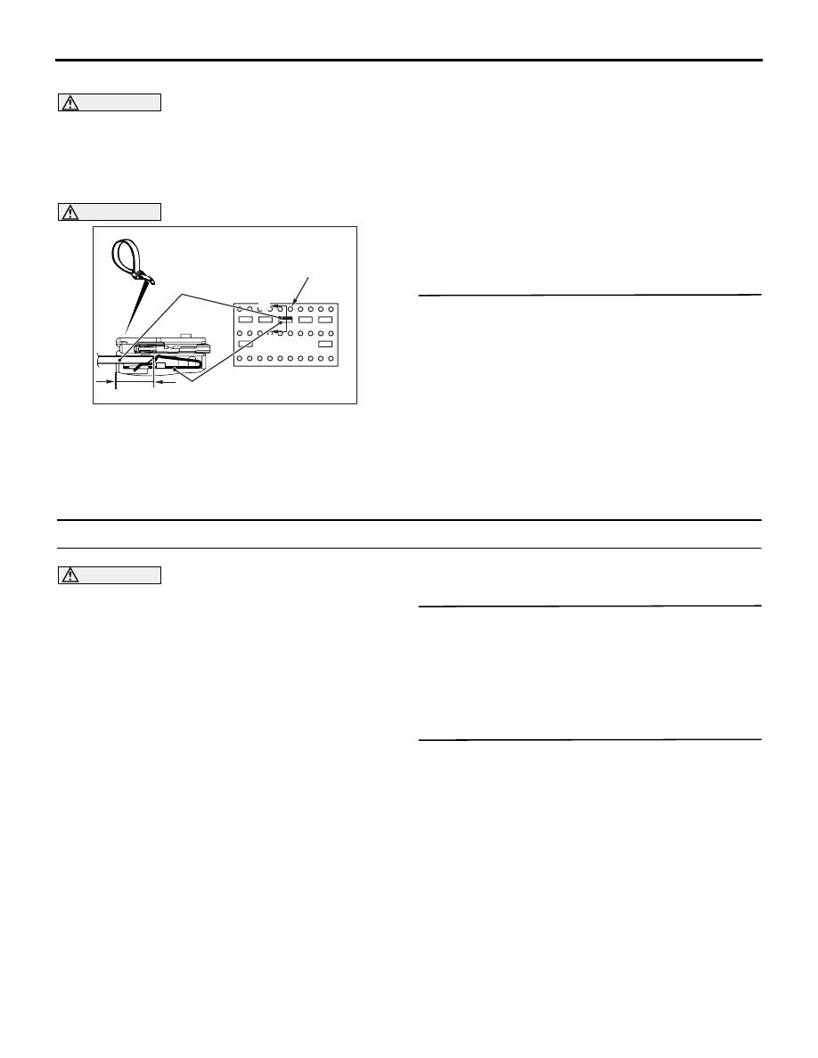
Harness side
connector (front view)
Section
A - A
Cable tie
Short spring
4 mm or more
Terminal
CAUTION
The short spring may not be released due to the
insufficient insertion. Therefore, insert the insu-
lator for 4 mm or more.
(4) Insert the insulator (width: 3 mm, thickness: 0.5
mm) such as cable tie between the DQ1-, DQ1+
line, and then release the short spring.
(5) Take the measurements below at the harness
side connector.
Continuity between DQ1-, DQ1+ line
OK: No continuity
Q: Is the check result normal?
YES :
Go to Step 7.
NO :
Repair the wiring harnesses between DQ1-,
DQ1+ line the clock spring connector and
the SRS-ECU connector.
STEP 7. Check whether the diagnosis code is
reset.
Q: Is the diagnosis code No. B1400 set?
YES :
Replace SRS-ECU (Refer to
NO :
Intermittent malfunction (Refer to GROUP
00
− How to Use
Troubleshooting/Inspection Service Points
−
How to Cope with Intermittent Malfunction ).
Code No.B1401 Driver's air bag module (squib) system (open circuit of squib circuit)
CAUTION
If the diagnosis code B1401 is set to SRS-ECU,
be sure to diagnose the CAN bus line.
OPERATION
Only when the frontal impact exceeding the threshold
is simultaneously detected (turned ON) by the front
impact sensor as well as by the analogue G-sensor
in SRS-ECU, the electric current is supplied from
SRS-ECU to the driver's air bag module (squib).
TROUBLE JUDGEMENT
The code is set when the open circuit occurs to the
SRS-ECU driver's air bag module (squib) circuit.
PROBABLE CAUSES
• Open circuit in the clock spring
• Open circuit due to improper neutral position of
the clock spring
• Open circuit to driver's air bag module (squib) cir-
cuit
• Disengaged driver's air bag module (squib) con-
nector
• Poor contact of connector
• Malfunction of SRS-ECU
DIAGNOSIS PROCEDURE
STEP 1. M.U.T.-III CAN bus diagnostics
Use M.U.T.-III to diagnose the CAN bus lines.
Q: Is the check result normal?
YES :
Go to Step 2
NO :
Repair the CAN bus line (Refer to GROUP
54C
− Troubleshooting ).
STEP 2. Check whether the diagnosis code is
reset.
(1) Connect the negative battery terminal.
(2) After erasing the diagnosis code memory, check
the diagnosis code again.
(3) Disconnect the negative battery terminal.
Q: Is the diagnosis code No. B1401 set?
YES :
Go to Step 3
NO :
Intermittent malfunction (Refer to GROUP
00
− How to Use
Troubleshooting/Inspection Service Points
−
How to Cope with Intermittent Malfunction ).