Mitsubishi Outlander (2013+). Manual - part 529


  Index      Mitsubishi     Mitsubishi Outlander - service repair manual 2013 year


Search            


Content   ..  527  528  529  530   ..


Mitsubishi Outlander (2013+). Manual - part 529


SUNROOF ASSEMBLY

BODY

42A-136

DISASSEMBLY SERVICE POINT

<<A>> BATTERY REMOVAL

CAUTION

Do not allow water or dust to enter the inside of 
the transmitter assembly when it is open. Also, 
do not touch the precision electronic device.

REASSEMBLY SERVICE POINT

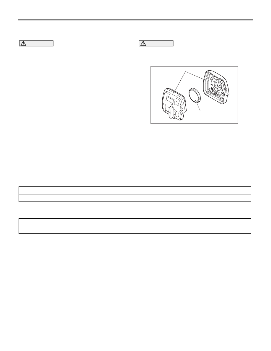
>>A<< BATTERY INSTALLATION

CAUTION

Do not allow water or dust to enter the inside of 
the transmitter assembly when it is open. Also, 
do not touch the precision electronic device.

AC304118 AF

+

Master key side

Upper cover side

Battery

Transmitter assembly

Install a battery to the transmitter assembly with its 
(+) side facing towards the upper cover side.

Battery required for replacement: Coin type 
battery CR1616

SUNROOF ASSEMBLY

SEALANT

M1426000500179

Item

Standard value

Sunroof assembly

Grease: Use resin 

− proof silicone grease

SERVICE SPECIFICATIONS

M1421000300857

Item

Standard value

Roof lid glass operation current (at 20

°C) A 

7 or less

SUNROOF ASSEMBLY

BODY

42A-137

SPECIAL TOOLS

M1426000600411

Tool

Number

Name

Use

ACB05421

MB992745

MB992746

MB992744

MB992747

MB992748

a

b

c

d

e

DO NOT USE

AB

a. MB992744
b. MB992745
c. MB992746
d. MB992747
e. MB992748

a. Vehicle 

communication 
interface-Lite 
(V.C.I.-Lite)

b. V.C.I.-Lite main 

harness A (for 
vehicles with CAN 
communication)

c. V.C.I.-Lite main 

harness B (for 
vehicles without 
CAN 
communication)

d. V.C.I.-Lite USB 

cable short

e. V.C.I.-Lite USB 

cable long

ECU check (M.U.T.-III diagnosis 
code display and service data 
display)

MB991910

MB991826

MB991955

MB991911

MB991824

MB991827

MB991825

a

b

c

d

e

f

DO NOT USE

SUNROOF ASSEMBLY

BODY

42A-138

MB991955

a: MB991824
b: MB991827
c: MB991910
d: MB991911
e: MB991825
f: MB991826

M.U.T.-III 
sub-assembly

a: Vehicle 

communication 
interface (V.C.I.)

b: M.U.T.-III USB 

cable

c: M.U.T.-III main 

harness A 
(Vehicles with CAN 
communication 
system)

d: M.U.T.-III main 

harness B 
(Vehicles without 
CAN 
communication 
system)

e: M.U.T.-III 

measurement 
adapter

f: M.U.T.-III trigger 

harness

CAUTION

For vehicles with CAN 
communication, use M.U.T.-III 
main harness A to send 
simulated vehicle speed. If you 
connect M.U.T.-III main harness 
B instead, the CAN 
communication does not 
function correctly.
ECU check (M.U.T.-III diagnosis 
code display and service data 
display)

MB991223

a

d

c

b

DO NOT USE

BA

MB991223

a. MB991219
b. MB991220
c. MB991221
d. MB991222

Wiring harness set

a. Check harness
b. LED harness
c. LED harness 

adapter

d. Probe

Continuity check and voltage 
measurement at wiring harness or 
connector

a. For checking connector pin 

contact pressure

b. For checking power supply 

circuit

c. For checking power supply 

circuit

d. For connecting a locally 

sourced tester

Tool

Number

Name

Use

MB992006

SUNROOF ASSEMBLY

BODY

42A-139

TROUBLESHOOTING

STANDARD FLOW OF DIAGNOSTIC 
TROUBLESHOOTING

M1426001700251

Refer to GROUP 00 

− How to Use Troubleshoot-

ing/Inspection Service Points, Contents of Trouble-
shooting .

DIAGNOSIS CODE CHART

M1426001900170

CAUTION

On troubleshooting, if the ignition switch is turned ON while disconnecting connector(s), diagnosis 
code(s) associated with other system may be set. On completion, confirm all systems for diagnosis 
code(s). If diagnosis code(s) are set, erase them all.

Diagnosis code No.

Diagnostic item

Reference 
page

L0630

S/R Power supply

P.42A-139

L0632

S/R Switch fail

P.42A-140

L0634

S/R Sensor signal

P.42A-140

L0637

S/R Position

P.42A-140

L0640

S/R Over load

P.42A-141

NOTE: S/R: Abbreviation of sunroof

DIAGNOSIS CODE PROCEDURES

CODE NO. L0630: S/R POWER SUPPLY

CAUTION

Before replacing the ECU, ensure that the input 
and output signal circuits are normal.

COMMENTS ON TROUBLE SYMPTOM

Current trouble

• If the terminal voltage at the sunroof ECU has 

been 8 V or lower, or 18V or higher for 60 sec-
onds, ETACS-ECU sets the diagnosis code No. 
L0630.

PROBABLE CAUSES

• Malfunction of the sunroof motor assembly

• Damaged wiring harness and connectors

DIAGNOSTIC PROCEDURE

STEP 1. Check of short to power supply, short to 
earth, and open circuit in IG1 line between 
sunroof motor assembly connector and fusible 
link.

Q: Is the check result normal?

YES : 

Go to Step 2.

NO : 

Repair the connector(s) or wiring harness.

STEP 2. Diagnosis code recheck
Recheck if the diagnosis code is set.
(1) Erase the diagnosis code.
(2) Turn the ignition switch from the LOCK (OFF) 

position to the ON position.

(3) Check if the diagnosis code is set.

MB992006

Extra fine probe

Continuity check and voltage 
measurement at wiring harness or 
connector

Tool

Number

Name

Use


Content   ..  527  528  529  530   ..