Mitsubishi Outlander (2013+). Manual - part 482
PARKING BRAKE CABLE
PARKING BRAKES
36-5
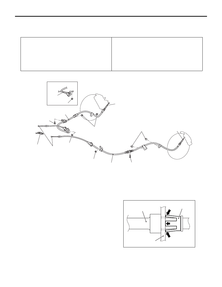
PARKING BRAKE CABLE
REMOVAL AND INSTALLATION
M1361001902026
Pre-removal operation
• Rear Floor Console Assembly Removal (Refer to GROUP
52A
− Rear Floor Console Assembly ).
• Second Seat Assembly Removal (Refer to GROUP 52A −
Second Seat Assembly ).
• Rear Floor Under Cover Removal (Refer to GROUP 51,
Under Cover ).
Post-installation operation
• Rear Floor Under Cover Removal (Refer to GROUP 51,
Under Cover ).
• Second Seat Assembly Installation (Refer to GROUP 52A
− Second Seat Assembly ).
• Rear Floor Console Assembly Installation (Refer to
GROUP 52A
− Rear Floor Console Assembly ).
• Parking brake lining seating procedure (Refer to
).
ACC00215
ACB04928
<2WD>
13 ± 2 N·m
1
2
2
13 ± 2 N·m
11 ± 2 N·m
11 ± 2 N·m
13 ± 2 N·m
13 ± 2 N·m
13 ± 2 N·m
AB
3
3
3
Equaliser
Removal steps
•
Release the parking brake lever.
•
Loosen the adjusting nut.
>>
B
<<
1.
Parking brake rear cable
connection (Parking brake lever
side)
•
Parking brake rear cable clamp
connection.
<<
A
>>
>>
A
<<
2.
Parking brake rear cable
connection (Rear brake caliper
assembly side)
3.
Parking brake rear cable
REMOVAL SERVICE POINTS
<<A>> PARKING BRAKE REAR CABLE
CONNECTION (REAR BRAKE CALIPER
ASSEMBLY SIDE) REMOVAL
ACB06000
Parking brake
rear cable
Parking brake lever
AC
Cable retainer
Compress the tabs on the cable retainer to pull out
the parking rear cable through the parking lever hole
of the rear brake caliper assembly.