Mitsubishi Outlander (2013+). Manual - part 456


  Index      Mitsubishi     Mitsubishi Outlander - service repair manual 2013 year


Search            


Content   ..  454  455  456  457   ..


Mitsubishi Outlander (2013+). Manual - part 456


WHEEL SPEED SENSOR

ANTI-SKID BRAKING SYSTEM (ABS)

35B-67

CAUTION

• Do not insert the rear wheel speed sensor at 

an angle or by prying the sensor because it 
may be possible that the O-ring of rear wheel 
speed sensor cannot be mounted properly.

• After the insertion, do not perform an align-

ment of mounting bolt hole positions by rotat-
ing the rear wheel speed sensor.

2. As shown in the figure, mount the rear wheel 

speed sensor while keeping the sensor 
perpendicular to the rear wheel hub assembly.

>>C<< REAR WHEEL SPEED SENSOR 
INSTALLATION

AC705246 AC

Rear wheel
hub assembly

Rear wheel speed sensor

Push the rear wheel speed sensor to the end and 
install it securely.

INSPECTION

M1352008400750

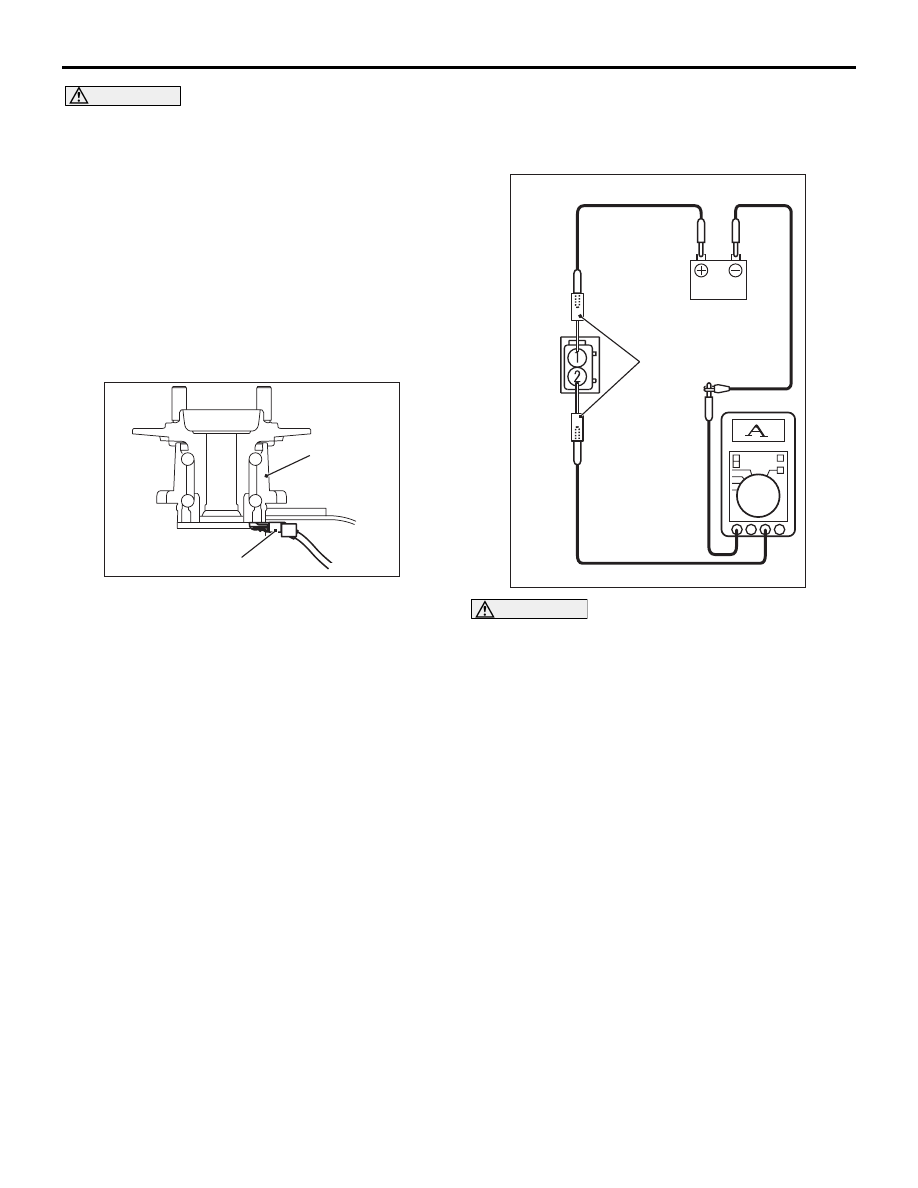
WHEEL SPEED SENSOR CURRENT 
CHECK

AC507330

MB992006

AB

CAUTION

• Do not connect the battery terminals in 

reverse as the wheel speed sensor may be 
damaged.

• When the current value is measured by the 

wheel speed sensor connector, measure it 
with the wheel speed sensor installed in the 
vehicle.

1. Connect the circuit tester to the wheel speed 

sensor using the special tool extra fine probe 
(MB992006), and measure the sensor current as 
a single unit.

Standard value: 5.9 to 8.4 mA or 11.8 to 16.8 
mA

2. If the measurement value is not within the 

standard value range, replace the wheel speed 
sensor with a new one.

WHEEL SPEED SENSOR

ANTI-SKID BRAKING SYSTEM (ABS)

35B-68

WHEEL SPEED SENSOR INSULATION 
CHECK

AC507331

MB992006

AB

<Front>

<Rear>

1. Connect the circuit tester to the wheel speed 

sensor using the special tool extra fine probe 
(MB992006), and measure the insulation 
resistance between the terminal No. 1/2 and the 
wheel speed sensor body as a single unit.

Standard value: 5 M

 or more

2. If the insulation resistance is not within the 

standard value range, replace the wheel speed 
sensor with a new one.

35C-1

GROUP 35C

ACTIVE STABILITY 

CONTROL SYSTEM 

(ASC)

CONTENTS

SERVICE SPECIFICATIONS. . . . . . .

35C-4

SPECIAL TOOL . . . . . . . . . . . . . . . . .

35C-4

TROUBLESHOOTING . . . . . . . . . . . .

35C-6

DIAGNOSIS TROUBLESHOOTING FLOW 

35C-6

PRECAUTIONS FOR DIAGNOSIS. . . . . . . 

35C-6

ABS WARNING LAMP, ASC WARNING/OPERATION 
LAMP AND BRAKE WARNING LAMP CHECK


 . . . . . . . . . . . . . . . . . . . . . . . . . . . . . . . . . . . . . .

35C-6

DIAGNOSTIC FUNCTION  . . . . . . . . . . . . . 

35C-7

DIAGNOSIS CODE CHART . . . . . . . . . . . . 

35C-15

DIAGNOSIS CODE PROCEDURES  . . . . . 

35C-18

Code No. C100A FL wheel speed sensor circuit


Code No. C1015 FR wheel speed sensor circuit


Code No. C1020 RL wheel speed sensor circuit


Code No. C102B RR wheel speed sensor circuit


 . . . . . . . . . . . . . . . . . . . . . . . . . . . . . . . . . . . . . .

35C-18

Code No. C1011 FL wheel speed sensor signal


Code No. C101C FR wheel speed sensor signal


Code No. C1027 RL wheel speed sensor signal


Code No. C1032 RR wheel speed sensor signal


 . . . . . . . . . . . . . . . . . . . . . . . . . . . . . . . . . . . . . .

35C-21

Code No. C1014 FL wheel speed sensor performance


Code No. C101F FR wheel speed sensor performance


Code No. C102A RL wheel speed sensor performance


Code No. C1035 RR wheel speed sensor performance


 . . . . . . . . . . . . . . . . . . . . . . . . . . . . . . . . . . . . . .

35C-24

Code No. C1041 FL wheel speed tone performance


Code No. C1042 FR wheel speed tone performance


Code No. C1043 RL wheel speed tone performance


Code No. C1044 RR wheel speed tone performance


 . . . . . . . . . . . . . . . . . . . . . . . . . . . . . . . . . . . . . .

35C-27

Code No. C1046 FL wheel speed sensor phase


Code No. C1047 FR wheel speed sensor phase


Code No. C1048 RL wheel speed sensor phase


Code No. C1049 RR wheel speed sensor phase


. . . . . . . . . . . . . . . . . . . . . . . . . . . . . . . . . . . . . . 

35C-29

Code No. C104B FL inlet valve


Code No. C104F FR inlet valve


Code No. C1053 RL inlet valve


Code No. C1057 RR inlet valve


Code No. C105F FL outlet valve


Code No. C1063 FR outlet valve


Code No. C1067 RL outlet valve


Code No. C105B RR outlet valve


Code No. C1200 FL-RR cut valve


Code No. C1204 FR-RL cut valve


Code No. C1208 FL-RR suction valve


Code No. C120C FR-RL suction valve  . . . . 

35C-32

Code No. C2104 Valve power supply circuit

35C-33

Code No. C1073 Motor drive circuit  . . . . . . 

35C-35

Code No. C2116 Pump motor voltage low  . 

35C-37

Code No. C121D Brake fluid pressure sensor circuit


. . . . . . . . . . . . . . . . . . . . . . . . . . . . . . . . . . . . . . 

35C-38

Code No. C121E Brake fluid pressure sensor


. . . . . . . . . . . . . . . . . . . . . . . . . . . . . . . . . . . . . . 

35C-39

Code No. C1000 Brake SW (stuck) . . . . . . . 

35C-41

Code No.C123B: System control too long . . 

35C-42

Code No. C2200 ECU internal error  . . . . . . 

35C-43

Code No. C2101 Power supply high voltage


. . . . . . . . . . . . . . . . . . . . . . . . . . . . . . . . . . . . . . 

35C-44

Code No. C1395 Incomplete Brake fluid filling


. . . . . . . . . . . . . . . . . . . . . . . . . . . . . . . . . . . . . . 

35C-45

Code No. C121C Torque request signal denied


. . . . . . . . . . . . . . . . . . . . . . . . . . . . . . . . . . . . . . 

35C-45

Code No.C2206 Re-execution of variant coding


. . . . . . . . . . . . . . . . . . . . . . . . . . . . . . . . . . . . . . 

35C-46

35C-2

Code No. C1210 Longitudinal G sensor input circuit


 . . . . . . . . . . . . . . . . . . . . . . . . . . . . . . . . . . . . . .

35C-47

Code No. C1242 Longitudinal G sensor signal


 . . . . . . . . . . . . . . . . . . . . . . . . . . . . . . . . . . . . . .

35C-48

Code No. C123C Sensor cluster malfunction


 . . . . . . . . . . . . . . . . . . . . . . . . . . . . . . . . . . . . . .

35C-49

Code No. C1392 Incomplete learn (Longitudinal G)


Code No. C1393 Incomplete learn neutral(Lateral G)


 . . . . . . . . . . . . . . . . . . . . . . . . . . . . . . . . . . . . . .

35C-51

Code No. C2204 Sensor cluster internal error


 . . . . . . . . . . . . . . . . . . . . . . . . . . . . . . . . . . . . . .

35C-52

Code No. C1219 Steering angle sensor signal


 . . . . . . . . . . . . . . . . . . . . . . . . . . . . . . . . . . . . . .

35C-53

Code No. C121A SAS initialization . . . . . . . 

35C-55

Code No. C2205: SAS internal error. . . . . . 

35C-56

Code No.C2002: Valve calibration not completed


 . . . . . . . . . . . . . . . . . . . . . . . . . . . . . . . . . . . . . .

35C-56

Code No. C1608 EEPROM fail . . . . . . . . . . 

35C-57

Code No.C1707: Implausible coding data. . 

35C-59

Code No. U0100 Engine CAN timeout


Code No. U0101 T/M CAN timeout


Code No. U0114 4WD CAN timeout


Code No. U0126 SAS CAN timeout


Code No. U0141 ETACS CAN timeout . . . . 

35C-60

Code No. U0401 Engine (CAN message). . 

35C-61

Code No. U0428 SAS (CAN message). . . . 

35C-62

Code No. U1073 Bus-off . . . . . . . . . . . . . . . 

35C-63

Code No. U1195 Coding not completed


Code No. U1197 Coding data unavailable . 

35C-64

TROUBLE SYMPTOM CHART. . . . . . . . . . 

35C-65

SYMPTOM PROCEDURES . . . . . . . . . . . . 

35C-66

Inspection Procedure 1: M.U.T.-III communication with 
ABS/ASC system is impossible. . . . . . . . . . 

35C-66

Inspection Procedure 2: ASC OFF lamp flashes at a 
rate of 2Hz. . . . . . . . . . . . . . . . . . . . . . . . . . 

35C-66

Inspection Procedure 3: Brake warning lamp stays ON 
with the parking brake lever released (ABS warning 
lamp is OFF).  . . . . . . . . . . . . . . . . . . . . . . . 

35C-67

Inspection Procedure 4: ABS warning lamp does not 
illuminate when ignition switch is turned to the ON 
position (engine stopped).. . . . . . . . . . . . . . 

35C-69

Inspection Procedure 5: Brake warning lamp does not 
illuminate when the ignition switch is turned to ON 
position (engine stopped).. . . . . . . . . . . . . . 

35C-70

Inspection Procedure 6: ABS warning lamp stays ON 
after the engine is started.. . . . . . . . . . . . . . 

35C-71

Inspection Procedure 7: ASC warning lamp stays ON 
after the engine is started.. . . . . . . . . . . . . . 

35C-72

Inspection Procedure 8: ASC OFF lamp stays ON after 
the engine is started.. . . . . . . . . . . . . . . . . . 

35C-73

Inspection Procedure 9: The stability control/TCL 
system cannot be disabled when ASC OFF switch is 

pressed for 3 seconds or more to turn the system OFF.


. . . . . . . . . . . . . . . . . . . . . . . . . . . . . . . . . . . . . . 

35C-75

Inspection Procedure 10: Abnormality in brake 
operation . . . . . . . . . . . . . . . . . . . . . . . . . . . 

35C-75

Inspection Procedure 11: ASC does not operate or 
faulty ASC operate. . . . . . . . . . . . . . . . . . . . 

35C-76

Inspection Procedure 12: ASC-ECU power supply 
circuit system.  . . . . . . . . . . . . . . . . . . . . . . . 

35C-77

Inspection Procedure 13: Steering wheel sensor power 
supply circuit system . . . . . . . . . . . . . . . . . . 

35C-79

Inspection Procedure 14: ABS/stability control/TCL 
operates too frequently. . . . . . . . . . . . . . . . . 

35C-80

Inspection Procedure 15: HSA (Hill Start Assist) does 
not work.  . . . . . . . . . . . . . . . . . . . . . . . . . . . 

35C-82

Inspection Procedure 16: HSA (Hill Start Assist) works 
on a flat road.. . . . . . . . . . . . . . . . . . . . . . . . 

35C-84

Inspection Procedure 17: The initial check sound of 
hydraulic unit is loud. . . . . . . . . . . . . . . . . . . 

35C-84

DATA LIST REFERENCE TABLE . . . . . . . . 

35C-85

ACTUATOR TEST TABLE  . . . . . . . . . . . . . 

35C-87

CHECK AT ECU TERMINALS  . . . . . . . . . . 

35C-88

ON-VEHICLE SERVICE . . . . . . . . . . .

35C-90

WHEEL SPEED SENSOR OUTPUT CURRENT 
MEASUREMENT. . . . . . . . . . . . . . . . . . . . . 

35C-90

HYDRAULIC UNIT (HU) CHECK  . . . . . . . . 

35C-90

MEASURES FOR DISCHARGED BATTERY


. . . . . . . . . . . . . . . . . . . . . . . . . . . . . . . . . . . . . . 

35C-93

ALL SENSOR CALIBRATION (G AND YAW RATE 
SENSOR, STEERING WHEEL SENSOR, BRAKE 
FLUID PRESSURE SENSOR)  . . . . . . . . . . 

35C-93

G AND YAW RATE SENSOR CALIBRATION


. . . . . . . . . . . . . . . . . . . . . . . . . . . . . . . . . . . . . . 

35C-93

STEERING WHEEL SENSOR CALIBRATION


. . . . . . . . . . . . . . . . . . . . . . . . . . . . . . . . . . . . . . 

35C-94

BRAKE FLUID PRESSURE SENSOR CALIBRATION


. . . . . . . . . . . . . . . . . . . . . . . . . . . . . . . . . . . . . . 

35C-94

ASC OFF SWITCH . . . . . . . . . . . . . . .

35C-95

REMOVAL AND INSTALLATION  . . . . . . . . 

35C-95

INSPECTION. . . . . . . . . . . . . . . . . . . . . . . . 

35C-95

HYDRAULIC UNIT  . . . . . . . . . . . . . . .

35C-95

REMOVAL AND INSTALLATION  . . . . . . . . 

35C-95

WHEEL SPEED SENSOR  . . . . . . . . .

35C-97

REMOVAL AND INSTALLATION <FRONT>


. . . . . . . . . . . . . . . . . . . . . . . . . . . . . . . . . . . . . . 

35C-97

REMOVAL AND INSTALLATION <REAR>. 

35C-97

INSPECTION. . . . . . . . . . . . . . . . . . . . . . . . 

35C-97


Content   ..  454  455  456  457   ..