Mitsubishi Outlander (2013+). Manual - part 430
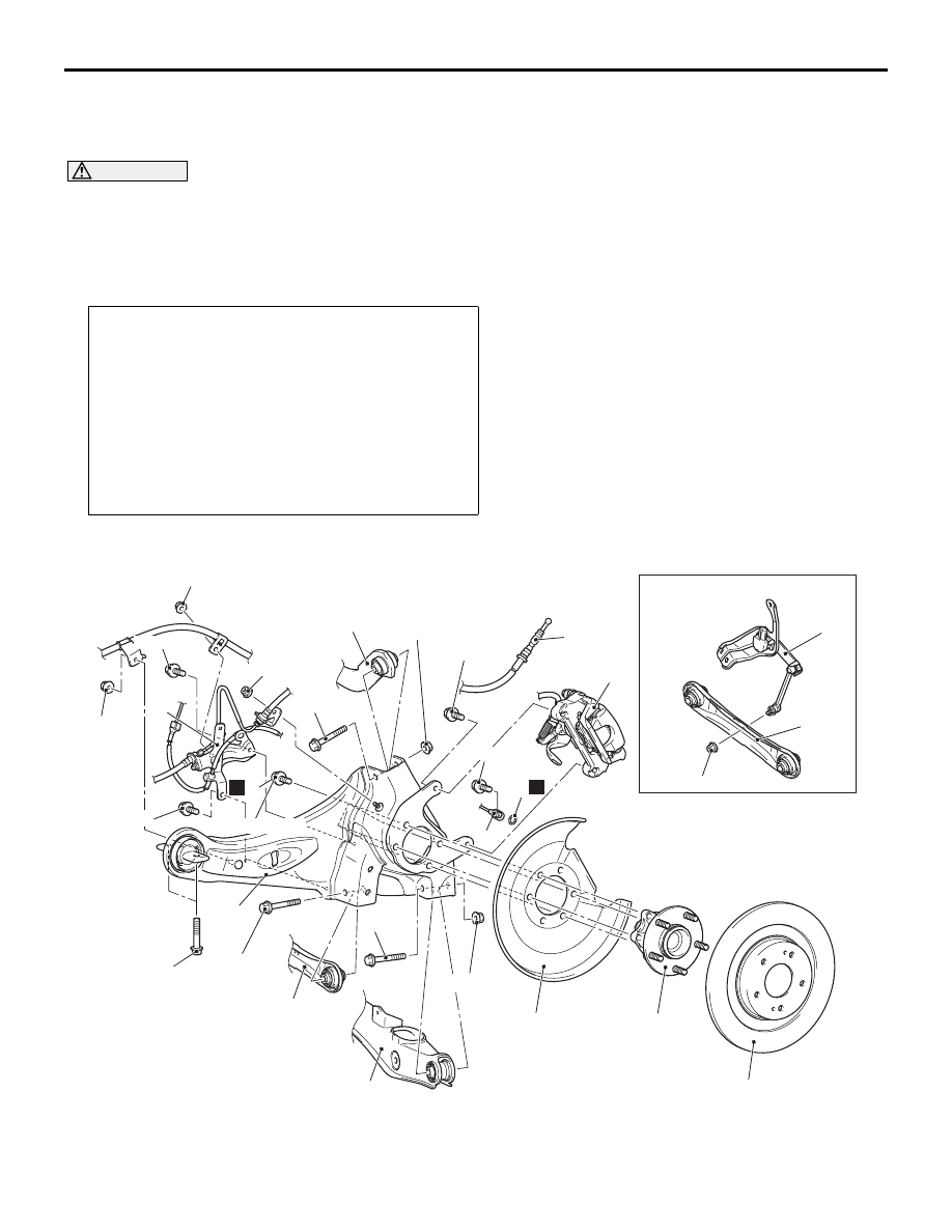
TRAILING ARM
REAR SUSPENSION
34-8
TRAILING ARM
REMOVAL AND INSTALLATION
M1341002201467
CAUTION
• The parts indicated by
*1
are the bolts/nuts with friction coefficient stabilizer. In removal, ensure
there is no damage, clean dust and soiling from the bearing and thread surfaces, and tighten them
to the specified torque.
•
Post-installation operation
• Rear Under Cover Removal and Installation (Refer to
GROUP 51, Under Cover ).
• Using your fingers, press the Ball Joint Dust Cover to
check for a crack or damage.
• Wheel Alignment Check and Adjustment (Refer to
.)
• Parking Brake Lever Stroke Check and Adjustment (Refer
to GROUP 36, On-vehicle Service
− Parking Brake Lever
Stroke Check and Adjustment .)
• Check the beam direction of the headlamp (Low beam)
(Refer to GROUP 54A
− Headlamp Aiming ).
The part indicated by
*2
is the bolt/nut with friction coefficient stabilizer. In removal, replace it with
new one.
<2WD>
ACB05587
1
11
9.5 ± 2.5 N·m
6
5
3
N
2
8.5 ± 1.5 N·m
71 ± 10 N·m
*1
55 ± 5 N·m
12
*1
13 ± 2 N·m
4
13 ± 2 N·m
13 ± 2 N·m
13 ± 2 N·m
8
N
95 ± 14 N·m
*2
14
13 ± 2 N·m
110 ± 11 N·m
*1
11
13
90 ± 9 N·m
*1
*1
71 ± 10 N·m
*1
10
9
7
AB