Mitsubishi Outlander (2013+). Manual - part 429


  Index      Mitsubishi     Mitsubishi Outlander - service repair manual 2013 year


Search            


Content   ..  427  428  429  430   ..


Mitsubishi Outlander (2013+). Manual - part 429


MB990326

ON-VEHICLE SERVICE

REAR SUSPENSION

34-4

ON-VEHICLE SERVICE

REAR WHEEL ALIGNMENT CHECK AND 
ADJUSTMENT

M1341011001278

1. Before the wheel alignment measurement, adjust 

the rear suspension, wheel, and tyres in good 
condition.

2. Park the vehicle on a level surface to measure the 

wheel alignment.

TOE-IN

Standard value:

At the centre of tyre tread: 3 

± 2 mm

Toe-angle (per wheel): 0 

° 02’  0 ° 12’

If it is out of the standard range, adjust as follows:

AC506806AB

Toe adjusting bolt

Turn the toe adjusting bolt (the mounting bolt inside 
the body on the control link) to adjust.

Left wheels: Clockwise (+) Toe in
Right wheels: Clockwise (

) Toe in

Toe-in varies approximately 2.6 mm (equivalent to 
0

°16' of the toe angle for one side) for each scale 

mark.

CAMBER

Standard value: 

0°30' ± 0°45'

NOTE: 

.

Difference between right and left wheels must be 
0

°

30' or less.

The camber is pre-adjusted at factory and is not 
adjustable.

AC305848 AC

Compensator

As for vehicles with aluminium wheel, use a compen-

sator to measure the camber and caster.

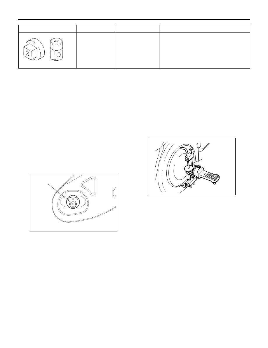
STABILIZER LINK BALL JOINT DUST 
COVER INSPECTION

M1341019100027

1. Using your fingers, press the dust cover to check 

for a crack or damage.

2. If the dust cover has a crack or damage, replace 

the stabilizer link.

NOTE: If the dust cover has a crack or damage, 
the ball joint could be damaged.

MB990326

Preload socket

Stabilizer link ball joint rotation torque 
measurement

Tool

Number

Name

Use

CONTROL LINK, UPPER ARM AND LOWER ARM

REAR SUSPENSION

34-5

CONTROL LINK, UPPER ARM AND LOWER ARM

REMOVAL AND INSTALLATION

M1341004800978

CAUTION

The parts indicated by * are the bolts/nuts with friction coefficient stabilizer. In removal, ensure there 
is no damage, clean dust and soiling from the bearing and thread surfaces, and tighten them to the 
specified torque.

Post-installation operation
• Using your fingers, press the Ball Joint Dust Cover to 

check for a crack or damage.

• Wheel alignment check and adjustment (Refer to 

P.34-4

.)

• Check the beam direction of the headlamp (Low beam) 

(Refer to GROUP 54A 

− Headlamp Aiming ).

ACB05563

*

*

9.5 ± 2.5 N·m

1

2

7

4

71 ± 10 N·m *

<Right side>

4

3

71 ± 10 N·m*

71 ± 10 N·m *

*

71 ± 10 N·m *

71 ± 10 N·m *

90 ± 9 N·m *

AB

*

71 ± 10 N·m*

2

5

8

39 ± 6 N·m

9

Control link and upper arm 
removal 

1.

Rear height sensor to control link 
connection <Vehicles with 
discharge headlamp>

2.

Plate

<<

A

>>

>>

B

<<

3.

Toe adjusting bolt

<<

A

>>

>>

B

<<

4.

Control link

Fuel tank vapour hose connection 
(Refer to GROUP 13B, Fuel tank  
<4WD>.)

>>

A

<<

5.

Upper arm

Control link and upper arm 
removal (Continued)

Lower arm removal steps 

1.

Rear height sensor to control link 
connection Vehicles with discharge 
headlamp>

6.

Stabilizer link connection

<<

B

>>

7.

Lower arm and trailing arm 
connection

<<

B

>>

8.

Shock absorber and lower arm 
connection

9.

Lower arm

CONTROL LINK, UPPER ARM AND LOWER ARM

REAR SUSPENSION

34-6

REMOVAL SERVICE POINT

<<A>> TOE ADJUSTING BOLT/CONTROL 
LINK REMOVAL

AC506821AB

Mating mark

Make a mating mark on the toe adjusting bolt, and 
remove the control link.

<<B>> LOWER ARM AND TRAILING 
ARM/SHOCK ABSORBER AND LOWER 
ARM DISCONNECTION

AC602688 AB

Mounting
bolt

Garage
jack

While jacking-up the lower arm with garage jack, 
remove the mounting bolts.

INSTALLATION SERVICE POINT

>>A<< UPPER ARM INSTALLATION

AC506825

Install the upper arm so that the hole faces the body 
side.

>>B<< TOE ADJUSTING BOLT/CONTROL 
LINK NSTALLATION

AC506821AB

Mating mark

Align the marks made on the toe adjustment bolt 

removal.

ACC00521

Control link

AB

Mark

Make sure that "FR" mark stamped on the control 

link points to the vehicle front.

CONTROL LINK, UPPER ARM AND LOWER ARM

REAR SUSPENSION

34-7

LOWER ARM BUSHING REPLACEMENT

M1341011800431

CAUTION

As the bushing has different outer diameters at 
both ends, be careful not to confuse the removal 
direction with the press-fit direction.

AC506997AB

MB992123

MB991449

MB991448

Driving Out

Lower arm

AC506996AB

MB991449

MB992123

MB991448

Lower arm

Press-Fitting

Use the following special tools to remove and 
press-fit the lower arm bushing:

• Arm bushing remover and installer (MB992123)

• Bushing remover and installer base (MB991448)

• Bushing remover and installer supporter 

(MB991449)


Content   ..  427  428  429  430   ..