Mitsubishi Outlander (2013+). Manual - part 422


  Index      Mitsubishi     Mitsubishi Outlander - service repair manual 2013 year


Search            


Content   ..  420  421  422  423   ..


Mitsubishi Outlander (2013+). Manual - part 422


TROUBLESHOOTING

WHEEL AND TYRE

31-5

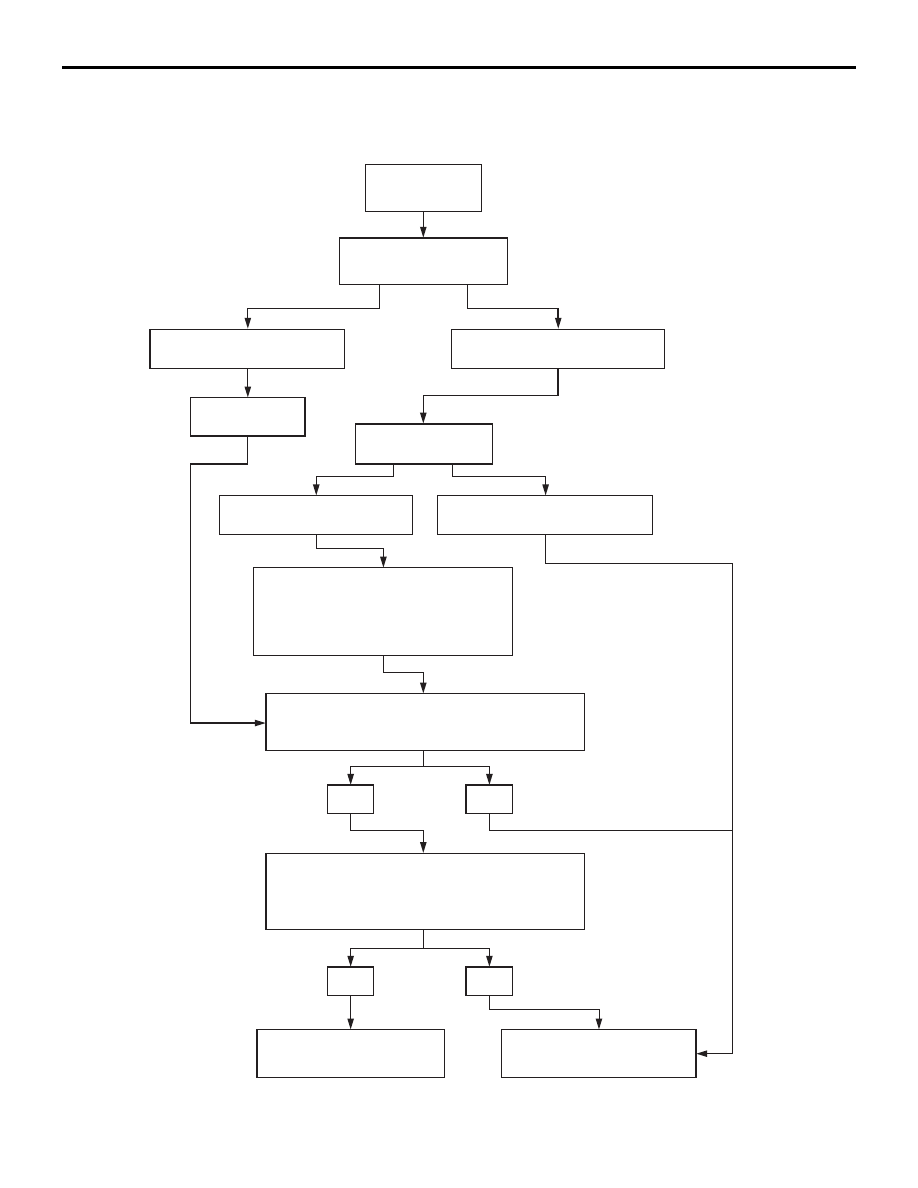
WHEEL BALANCER CALIBRATION 
CHECKING FLOW CHART

AC502720AB

Balance wheel.

Rotate wheel 1/2 turn.

Imbalance = 5 g or less

Imbalance = more than 5 g

Rebalance wheel.

Rotate wheel 1/4 turn.

Imbalance = 5 g or less

Imbalance = more than 5 g

Verify wheel is properly centred.
Verify cones, cup, and wing nut are clean,
undamaged, and appropriate for wheel.
Make necessary corrections, then recheck
wheel balance.

Attach a 5 g weight to the outer rim.
Is the imbalance 5 ± 2 g at 170 – 190˚ away from the
5 g weight? 

YES

NO

Attach a 5 g weight to the inner rim at 180˚ opposite 
the weight on the outer rim.
Is the imbalance 5 ± 2 g at 170 – 190˚ away from 
both 5 g weights?

YES

NO

Balancer does not require
calibration.

Balancer requires calibration.
Contact balancer manufacturer.

ZERO CALIBRATION 
CHECK

STATIC BALANCE 
CHECK

DYNAMIC BALANCE 
CHECK

ON-VEHICLE SERVICE

WHEEL AND TYRE

31-6

ON-VEHICLE SERVICE

TYRE INFLATION PRESSURE CHECK

M1311000900572

NOTE: For information on tyre inflation pressure, 
refer to the label attached to the centre pillar on the 
driver's side.

TYRE WEAR CHECK

M1311001000635

Measure the tread depth of the tyres.

Minimum limit: 1.6 mm

If the remaining tread depth is less than the minimum 
limit, replace the tyre.

NOTE: When the tread depth of the tyres is reduced 
to 1.6 mm or less, wear indicators will appear.

WHEEL RUNOUT CHECK

M1311001100654

ACX00651AB

Lateral

Radial

Jack up the vehicle so that the wheels are clear of 
the floor. While slowly turning the wheel, measure 
wheel runout with a dial indicator.

Limit:

Item

Steel wheel

Aluminium 
wheel

Radial runout 
mm

1.2

1.0

Lateral runout 
mm

1.2

1.0

If wheel runout exceeds the limit, replace the wheel.

WHEEL AND TYRE

INSTALLATION SERVICE POINT

M1311001300528

Tighten the wheel nuts to the specified torque.

Tightening torque: 98 

± 10 Nm

SPARE TYRE CARRIER

WHEEL AND TYRE

31-7

SPARE TYRE CARRIER

REMOVAL AND INSTALLATION

M1311006700305

AC506550

25 ± 4 N·m

3

1

AC

4

12 ± 3 N·m

6

5

7

12 ± 3 N·m

2

5

8

Vehicles front


Removal steps 

1.

Spare tyre carrier holder

2.

Spare tyre carrier spacer

3.

Spare tyre carrier bolt

4.

Spare tyre carrier washer

5.

Spare tyre carrier pin

6.

Spare tyre carrier

7.

Spare tyre carrier bracket (LH)

8.

Spare tyre carrier bracket (RH)

 Removal 

steps 

(Continued)

32-1

GROUP 32

POWER PLANT 

MOUNT

CONTENTS

SPECIAL TOOL . . . . . . . . . . . . . . . . .

32-2

ENGINE MOUNTING . . . . . . . . . . . . .

32-2

REMOVAL AND INSTALLATION . . . . . . . . 

32-2

TRANSMISSION MOUNTING . . . . . .

32-3

REMOVAL AND INSTALLATION  . . . . . . . . 

32-3

ENGINE ROLL STOPPER ROD. . . . .

32-4

REMOVAL AND INSTALLATION  . . . . . . . . 

32-4

CROSSMEMBER . . . . . . . . . . . . . . . .

32-5

REMOVAL AND INSTALLATION  . . . . . . . . 

32-5


Content   ..  420  421  422  423   ..