Mitsubishi Outlander (2013+). Manual - part 404


  Index      Mitsubishi     Mitsubishi Outlander - service repair manual 2013 year


Search            


Content   ..  402  403  404  405   ..


Mitsubishi Outlander (2013+). Manual - part 404


DRIVESHAFT ASSEMBLY

REAR AXLE <4WD>

27B-20

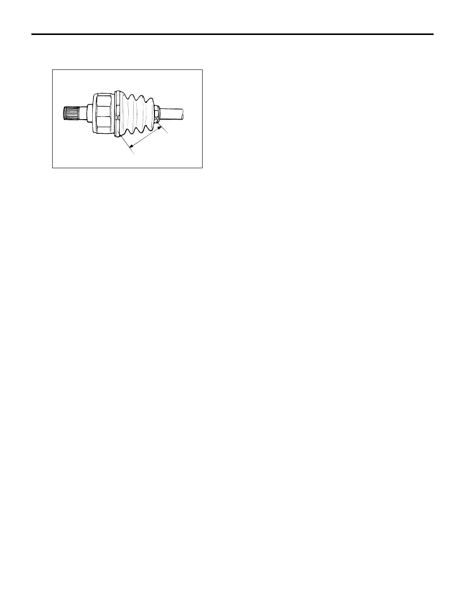
>>B<< ETJ BOOT BAND (SMALL)/ETJ 
BOOT BAND (LARGE) TIGHTENING

AC102657AB

A

Adjust the distance between the boot bands to the 
standard value to adjust the air volume inside the 
ETJ boot to the specified value, then be sure to 
tighten the ETJ boot band (large) and ETJ boot band 
(small).

Standard value (A): 75 

± 3 mm

DIFFERENTIAL CARRIER ASSEMBLY

REAR AXLE <4WD>

27B-21

DIFFERENTIAL CARRIER ASSEMBLY

REMOVAL AND INSTALLATION

M1271005300392

CAUTION

Pre-removal operation
• Spare tyre and spare tyre carrier removal (Refer to 

GROUP 31, Spare Tyre Carrier ).

• Centre exhaust pipe and main muffler removal (Refer to 

GROUP 15, Exhaust Pipe and Muffler ).

• Drain differential gear oil.
• Drive shaft removal (Refer to 

P.27B-14

).

Post-installation operation
• Drive shaft installation (Refer to 

P.27B-14

).

• Fill the differential gear oil.

• Centre exhaust pipe and main muffler installation (Refer 

to GROUP 15, Exhaust Pipe and Muffler ).

• Spare tyre and spare tyre carrier installation (Refer to 

GROUP 31, Spare Tyre Carrier ).

ACB05750AB

54 ± 5 N·m

95 ± 14 N·m

71 ± 10 N·m

1

N

32 ± 2 N·m

71 ± 10 N·m

95 ± 14 N·m

110 ± 11 N·m

9.8 ± 1.9 N·m

2

3

N

32 ± 2 N·m

4

7

5

6

*

*

*

7.0 ± 3.0 N·m

9

10

11

13

8

9

10

11

12

13

14

The parts indicated by * are the bolts with friction coefficient stabilizer. In removal, ensure there is 
no damage, clean dust and soiling from the bearing and thread surfaces, and tighten them to the 
specified torque.

Removal steps 

<<

A

>>

1.

Propeller shaft connection

2.

Filler plug

3.

Gasket

4.

Drain plug

5.

Gasket

6.

Cover

7.

Electronic control coupling 
harness connection, breather 
hose connection

Removal steps (Continued)

DIFFERENTIAL CARRIER ASSEMBLY

REAR AXLE <4WD>

27B-22

REMOVAL SERVICE POINT

<<A>> PROPELLER SHAFT DISCONNEC-
TION

ACB05381

Mating marks

AB

1. Put mating marks on the flange yoke and the 

electronic control coupling.

2. Hold the disconnected propeller shaft with a wire 

so that it will not be bent sharply.

INSTALLATION SERVICE POINT

>>A<< DIFFERENTIAL CARRIER ASSEM-
BLY INSTALLATION

ACC00420

Electronic control coupling

A

AB

1. Check that the length of the electronic control 

coupling stud bolt (A) is within the standard value 
range.

Standard value: 21.6 

 24.4 mm

2. If the length exceeds the standard value, replace 

the stud bolt.

Tightening torque: 15 

± 3 N

NOTE: When replacing the stud bolts, always 
clean the stud bolt threaded holes.

8.

Differential to rear suspension 
crossmember connecting bolt

9.

Weight

10. Lower stopper
11. Upper stopper

>>

A

<<

12. Differential carrier assembly
13. Differential mount bracket (LH/RH)
14. Differential bracket

Removal steps (Continued)

DIFFERENTIAL CARRIER ASSEMBLY

REAR AXLE <4WD>

27B-23

DISASSEMBLY

M1271005400225

ACB05751

14

12

11

29

5

20

33

1

7

8

N

N

4

N

N

N

19

18

17

10

AB

3

2

N

6

9

10

11

13

12

15

16 17

18

19

20

21

22

23

24

25

26

27

28

30

31

32

13

Disassembly steps 

1.

Filler plug

2.

Gasket

3.

Drain plug

4.

Gasket

5.

Electronic control coupling

6.

Wave washer

7.

Differential cover assembly

8.

Vent plug

9.

Oil seal

<<

A

>>

Pre-disassembly check

<<

B

>>

10. Differential case assembly

<<

B

>>

11. Differential side bearing spacer

<<

B

>>

12. Differential side bearing outer race

<<

C

>>

13. Differential side bearing inner race

<<

D

>>

14. Drive gear

<<

E

>>

15. Lock pin
16. Pinion shaft
17. Pinion gear
18. Pinion washer
19. Side gear
20. Side gear spacer

21. Differential case

<<

F

>>

22. Differential nut
23. Drive pinion assembly
24. Drive pinion front shim (for drive 

pinion rotation torque adjustment)

25. Drive pinion spacer

<<

G

>>

26. Drive pinion rear bearing inner 

race

27. Drive pinion rear shim (for drive 

pinion height adjustment)

28. Drive pinion
29. Oil seal
30. Drive pinion front bearing inner 

race 

<<

H

>>

31. Drive pinion front bearing outer 

race

<<

I

>>

32. Drive pinion rear bearing outer 

race

33. Differential carrier

Disassembly steps (Continued)


Content   ..  402  403  404  405   ..