Mitsubishi Outlander (2013+). Manual - part 401
AC302114
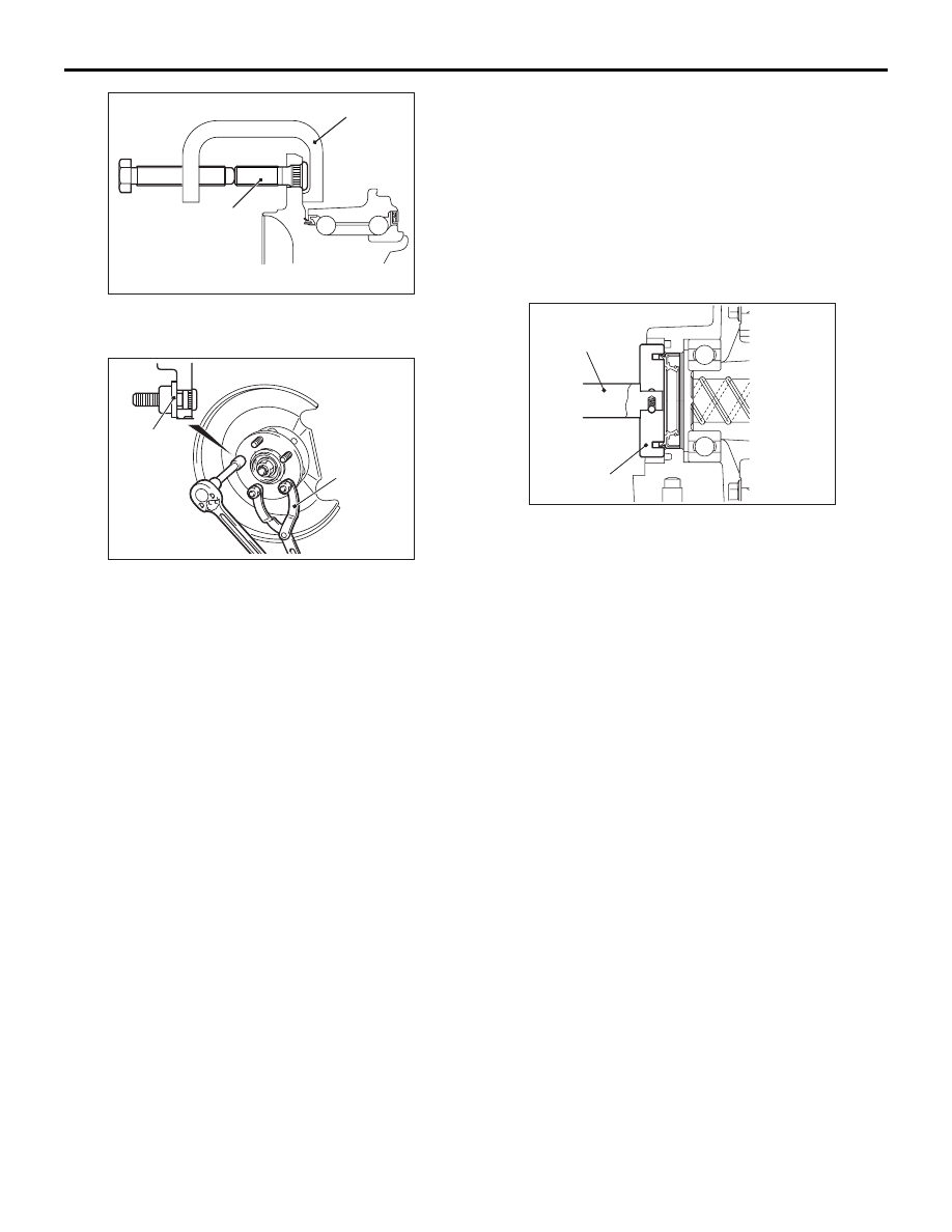
MB991618
AD
Hub bolt
ON-VEHICLE SERVICE
REAR AXLE <4WD>
27B-8
2. Use special tool hub bolt remover (MB991618) to
remove the hub bolt.
ACB05745
MB990767
Plain washer
AB
3. After fixing the hub using special tool front hub
and flange yoke holder (MB990767), install the
plain washer to the new hub bolt, and tighten the
bolt with a nut.
4. Install the brake disc, caliper assembly and
tighten the caliper assembly mounting bolts to the
specified torque.
Tightening torque: 58
± 7 N⋅m
DIFFERENTIAL CARRIER OIL SEAL
REPLACEMENT
M1271005100127
1. Remove the driveshaft (Refer to
2. Remove the differential carrier oil seal.
AC505816
MB990938
MB991115
AB
3. Use the following special tools to drive in the oil
seal:
• Installer bar (MB990938)
• Oil seal installer (MB991115)
4. Coat the oil seal lip and the oil seal contact
surface on the driveshaft with the multi-purpose
grease.
5. Replace the driveshaft circlip with a new one, and
install the driveshaft (Refer to
).