Mitsubishi Outlander (2013+). Manual - part 390


  Index      Mitsubishi     Mitsubishi Outlander - service repair manual 2013 year


Search            


Content   ..  388  389  390  391   ..


Mitsubishi Outlander (2013+). Manual - part 390


AC808144AC

<Correct state>

Oil seal

AC510591AB

Oil seal lip
protruded

<Incorrect
state>

ON-VEHICLE SERVICE

PROPELLER SHAFT

25-3

3. Check the propeller shaft universal joint, oil seal 

for crack or damage. If abnormality is recognized, 
replace the propeller shaft with a new one.

PROPELLER SHAFT UNIVERSAL JOINT 
PLAY CHECK

1. Place the gearshift lever to the selector lever to 

the "N" position.

AC501206AC

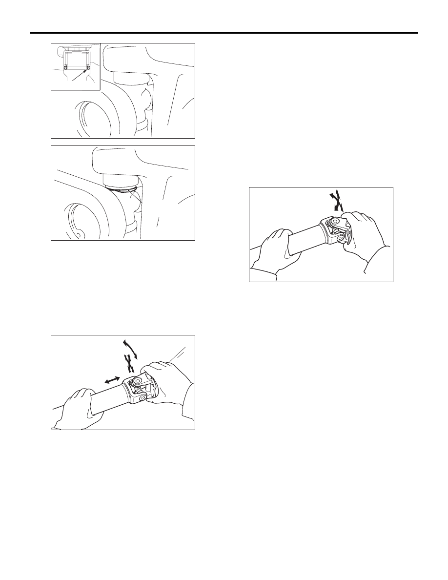
2. Hold the tube of propeller shaft by one hand, and 

apply force by the other hand to the flange yoke or 
sleeve yoke in rotating direction, axial direction, 
and perpendicular direction for checking 
looseness. If looseness is recognized, replace the 
propeller shaft with a new one.

PROPELLER SHAFT UNIVERSAL JOINT 
FLECTION CHECK

1. Place the gearshift lever to the selector lever to 

the "N" position.

2. Make phase alignment marks on the flange yoke 

and differential companion flange and disconnect 
the flange yoke.

AC510592

3. Hold the tube of propeller shaft by one hand, and 

apply force by the other hand to the flange yoke in 
flection direction for checking flection. If showing a 
sign of catch in the flection direction is 
recognized, replace the propeller shaft with a new 
one.

PROPELLER SHAFT

PROPELLER SHAFT

25-4

PROPELLER SHAFT

REMOVAL AND INSTALLATION

M1251001001271

Pre-removal and Post-installation operation
• Engine Room Under Cover Removal and Installation 

(Refer to GROUP 51, Under Cover .)

• Transfer Oil Draining and Filling (Refer to GROUP 23A, 

On-vehicle Service, Transfer Oil Change .)

ACA01525

54 ± 5 N·m

AB

41 ± 5 N·m

41 ± 5 N·m

1

4

4

13 ± 2 N·m

3

3

2

5

6

6

Gear oil:
Hypoid gear oil API classification GL-5
SAE80

4

5

4

Removal steps 

<<

A

>>

>>

B

<<

1.

Flange yoke and electronic control 
coupling connecting nut

2.

Heat protector

3.

Bolt

4.

Insulator

5.

Spacer

<<

B

>>

>>

A

<<

6.

Propeller shaft assembly

REMOVAL SERVICE POINTS

<<A>> FLANGE YOKE AND ELECTRONIC 
CONTROL COUPLING CONNECTING NUT 
REMOVAL

ACB05381

Mating marks

AB

Put mating marks on the flange yoke and the elec-
tronic control coupling, then remove the connecting 
nuts.

PROPELLER SHAFT

PROPELLER SHAFT

25-5

<<B>> PROPELLER SHAFT ASSEMBLY 
REMOVAL

CAUTION

If the joint assembly is bent, it may be damaged 
when pinching the joint boots.

ACB05382

Joint boots

Joint assembly

Waste

AB

1. Insert a waste or similar materials into the joint 

boots, and remove the propeller shaft assembly 
by aligning the front propeller shaft with the rear 
shaft. 

AC505520

AB

MB991193

2. Using special tool plug (MB991193), cover the 

transfer case to prevent the entry of foreign 
materials.

INSTALLATION SERVICE POINT

>>A<< PROPELLER SHAFT ASSEMBLY 
INSTALLATION

CAUTION

AC505521

AB

Oil seal

Transfer

Do not damage the oil seal lip of the transfer.

• The mounting bolt and nut may be loosened if 

oil or grease is stuck on the threads of the 
bolt and nut. Tighten them after degreasing 
the threads.

• If the joint assembly is bent, it may be dam-

aged when pinching the joint boots.

>>B<< PROPELLER SHAFT FLANGE 
YOKE AND REAR DIFFERENTIAL 
CONNECTION NUT INSTALLATION

If the propeller shaft is reused, align the mating 
marks and install the connecting nuts.

Tightening torque: 54 

± 5 Nm

INSPECTION

M1251001100703

DEFLECTION OF THE PROPELLER 
SHAFT

ACX00643

Check the deflection of the front and rear shafts.

Limit
Front : 1.0 mm
Rear : 1.0 mm

26-1

GROUP 26

FRONT AXLE

CONTENTS

SERVICE SPECIFICATION(S)  . . . . .

26-2

LUBRICANT(S)  . . . . . . . . . . . . . . . . .

26-2

SPECIAL TOOL(S)  . . . . . . . . . . . . . .

26-2

ON-VEHICLE SERVICE. . . . . . . . . . .

26-5

WHEEL BEARING AXIAL PLAY CHECK . . 

26-5

HUB BOLT REPLACEMENT  . . . . . . . . . . . 

26-5

FRONT AXLE HUB ASSEMBLY . . . .

26-7

FRONT AXLE HUB ASSEMBLY REMOVAL AND 

INSTALLATION . . . . . . . . . . . . . . . . . . . . . . 

26-7

FRONT AXLE HUB ASSEMBLY DISASSEMBLY AND 
REASSEMBLY  . . . . . . . . . . . . . . . . . . . . . . 

26-11

DRIVESHAFT ASSEMBLY. . . . . . . . .

26-15

DRIVESHAFT ASSEMBLY REMOVAL AND 
INSTALLATION . . . . . . . . . . . . . . . . . . . . . . 

26-15

DRIVESHAFT ASSEMBLY DISASSEMBLY AND 
REASSEMBLY <2WD> . . . . . . . . . . . . . . . . 

26-21

DRIVESHAFT ASSEMBLY DISASSEMBLY AND 
REASSEMBLY <4WD> . . . . . . . . . . . . . . . . 

26-25

EBJ BOOT REPLACEMENT . . . . . . . . . . . . 

26-27


Content   ..  388  389  390  391   ..